Definitely, we had the same problem and with the previous v1.16 fw. It seems to be a XMOS update problem, a google search gives a lot same issues!
And now I have the same problem with the new version...
The problem Demian has is not the same as what may be experienced by others here. His unit has an older firmware version with a specific issue, which I will try to solve.
Looking at the AK5394A data sheet, the filter is enabled if pin 19 ("HPFE") is high, and disabled if the pin is low. Hmmm... can I just pull the HPFE pin in your photo to GND without breaking stuff or affecting performance in any other way? Jens, what are your thoughts about this?
No, don't connect the "HPFE pin" to GND

The pin closest to "HPFE" is not HPFE, but a 3.3 V supply!
I generally don't recommend modifying the RTX6001 except for the changes suggested by RTX. If you destroy it, the warranty will not cover it.
Thanks, Demian,
I didn't find that in my Googling last night. I did some xmos page saying they where compatible with the standard USB DFU protocol. So it does give me some hope that it could be done using python and libusb, which should make it portable to the various OS's.
I hope to have some time to try it out. That will also give me a good reason to get the RTX out of the box
Mogens
Hi Jens,
I used to have some frequency pickup close to 50 KHz. The shield modification has reduced this to a lower amplitude. The shields are doing their job it would seem.
-Chris
Glad to hear it.
I dropped in the shields a couple of days ago.
But I did not have enough time to do a comparison.
No, don't connect the "HPFE pin" to GND
The pin closest to "HPFE" is not HPFE, but a 3.3 V supply!
Is there another spot to get to the real HPFE? Directly at the DAC chip?
Would grounding the HPFE pin even work, or would it upset the electronics around it?
If you destroy it, the warranty will not cover it.
Sure! I am not asking for an official recommendation by RTX. Just trying to understan if such a mod will automatically destroy the RTX, or it there is any chance this might actually be workable somehow.
Why are you after DC response? What are you looking for with it?
A better way (this may sound crazy but it isn't) would be to get a good reasonably fast sampling DVM and sync that for the DC info you are looking for. The DC drift and offset that will forever hound measurements with an audio ADC will be gone.
A better way (this may sound crazy but it isn't) would be to get a good reasonably fast sampling DVM and sync that for the DC info you are looking for. The DC drift and offset that will forever hound measurements with an audio ADC will be gone.
There should be no need to do something near the ADC chip. As you see (or guess due to bad resolution) here
GB for RTX6001 Audio Analyzer with AK5394A and AK4490
all the pins routed out for make the settings somehow.
One should only need to remove the heat sink be able to trace routes and reverse engineer it ... unless Jens gives the necessary infos.
GB for RTX6001 Audio Analyzer with AK5394A and AK4490
all the pins routed out for make the settings somehow.
One should only need to remove the heat sink be able to trace routes and reverse engineer it ... unless Jens gives the necessary infos.
Hi Demian,
I couldn't agree more! A real DC response is best done with a meter. Most of the good ones now have moving average, can export the measurements and some can even do statistics.
Wandering DC offsets make life hell for taking measurements and are best viewed as noise.
-Chris
I couldn't agree more! A real DC response is best done with a meter. Most of the good ones now have moving average, can export the measurements and some can even do statistics.
Wandering DC offsets make life hell for taking measurements and are best viewed as noise.
-Chris
That is like saying HF is noise on a scope
This may be true and therefore a scope has switchable BW limit filters. It may false, therefore the filters are switchable.
In case of the RTX it is only a digital filter. So you throw away available information. In some cases this might make sense, but it should be the users choice and probably the better location to filter data would be the software you use to interpret the measurements.
The suggestion to use a meter for that has it merits, but you need to sync two instruments which makes handling more complicated, and the precision of the meter is also limited if you only have a fraction of a second for each measurement.
Hi zfe,
You need another meter. Mine will sample several times a second at 5 1/2 digits of resolution, maybe even with 6 1/2 digits of resolution. If I go down to 4 1/2 digits of resolution I'll have a ton of readings. My meter is over 20 years old, or close to that. It's an HP 34401A, I bought it when they first came out.
This low a frequency will not have any connection to whatever signal a device is reproducing unless it is a trend, in which case you can sync it with your eyes and maybe a stopwatch. You can set set a trigger on most new (good) multimeters that will then sync the start of readings with the application of the signal as well.
A high enough frequency is noise when measuring audio signals. These would be oscillations or ringing in the circuit, or radiated noise it is picking up from somewhere. These signals are of interest in developing or repairing a circuit, but you would tend to use an instrument with wider bandwidth than the RTX-6001. The Keysight u8903B with the 1.5 MHz option would fit that, better still a spectrum analyser. Even some oscilloscopes would suit this application.
The RTX is extremely good at the job it was designed to do. But messing up the data with drifting offset won't do you any favors. In fact you may want to limit the low frequency response even higher in the case of a faster drifting offset.
Now for the real kicker. An FFT has a high DC artifact that exists no matter how you generate the display. It's in the math. That is why on any spectrum analyser that starts at 0 Hz has a vertical line that has nothing to do with the signal. You couldn't show a DC offset even if you wanted to. Anything that could possibly be displayed wouldn't have any connection to actual circuit conditions. You would have to use a meter or oscilloscope to capture any DC information anyway.
-Chris
Audio ADCs are not generally designed for measurements down to DC which is why they have the digital HPF to remove DC offsets and drift, as others have pointed out if you attempt DC measurements you will get drifts and offsets that are hard to deal with, the signal path will also contribute its share of offset as well.
The RTX and most audio analyzers are not designed to do DC measurements.
The advice to use an instrument intended for precise DC measurements is well founded.
If you are concerned about very low frequency phase shift there are ways to deal with that using a reference measurement in parallel with the DUT measurement (Audiotester at least supports this)
... Now for the real kicker. An FFT has a high DC artifact that exists no matter how you generate the display. It's in the math. That is why on any spectrum analyser that starts at 0 Hz has a vertical line that has nothing to do with the signal. You couldn't show a DC offset even if you wanted to.
Tss, tss, don't blame math.

The DFT is invertible, so different sequences have different transforms and each value has to be finite.
Moreover it is easy to compute the transform of a constant sequence (c,c,c...) it is (cN,0,0,...), N the length of the sequence. As the DFT is linear a DC offset just adds that to the zero-coefficient of the transform without DC offset.
In case you use windowing, the constant sequence (c,c,c...) will get the window scaled by c and thus its transform is the scaled transform of the window, which will be added to the transform without DC offset.
Last edited:
The RTX is extremely good at the job it was designed to do. But messing up the data with drifting offset won't do you any favors. In fact you may want to limit the low frequency response even higher in the case of a faster drifting offset.
If drift is an issue, I agree it's better to use something else (like a meter) to get reliable readings. But is drift really an issue? Do we know? Until a few days ago I thought the RTX would read the DC level as long as the DC blocker is switched off on the front panel (yes, I should probably RTFM). It's a bit confusing to have no DC in the measurements even if the front panel switch is set to pass DC.
Now for the real kicker. An FFT has a high DC artifact that exists no matter how you generate the display. It's in the math.
Why FFT? As zfe said, the data processing and interpretation is up to the user and the software. And even if you do an FFT of the RTX readings, that should nicely cope with DC. Depending on the FFT implementation, the first FFT bin is usually just the mean of the data values, which is the DC level during the measurement. There is nothing wrong with DC in a Fourier spectrum.
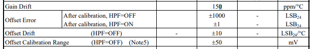
Attached are the specs for the ADC. The input JFETs will have dc offset and dc drift values as well. 20 uV/ degree C is typical and then only if the rest of the circuitry was optimized for DC stability. In this case the goal is linearity. For good DC you really need a chopper stabilized amp and an ADC with an active auto zero. Neither of which are appropriate for audio.
Attachments
Hi mbrennwa,
The rest of what Demian said is dead on the money. Not only that, but what possible use would a line of variable height at 0 Hz be to you or anyone else?? A meter is by far a better instrument for that. In fact, we often average the signal over a number of readings for low level DC measurements to reduce noise to see the true DC levels there are. Even analogue front ends (thermocouple or PH measurements) average the reading with an input filter. That is what a LP filter does to reduce HF interference.
-Chris
So, how do you expect to get a frequency vs amplitude display without using FFT. It will have a DC "spike" that is unavoidable.Why FFT? As zfe said, the data processing and interpretation is up to the user and the software. And even if you do an FFT of the RTX readings, that should nicely cope with DC.
The rest of what Demian said is dead on the money. Not only that, but what possible use would a line of variable height at 0 Hz be to you or anyone else?? A meter is by far a better instrument for that. In fact, we often average the signal over a number of readings for low level DC measurements to reduce noise to see the true DC levels there are. Even analogue front ends (thermocouple or PH measurements) average the reading with an input filter. That is what a LP filter does to reduce HF interference.
-Chris
So, how do you expect to get a frequency vs amplitude display without using FFT.
I don't. But who says I want frequency vs. amplitude always? There are so many ways of looking at measurement data (time domain, frequency domain, whatever).
It will have a DC "spike" that is unavoidable.
If there's DC in the signal, sure, that's what it should be.
what possible use would a line of variable height at 0 Hz be to you or anyone else??
It tells you how much DC is in the data. The DC level may not be interesting for the tests you have in mind, but that does not mean that others are not interested in DC.
A meter is by far a better instrument for that.
Better in what way? Better accuracy and precision? Ergonmics? Cost? Etc.
I am not saying we should all go ahead and modify the RTX to do DC with the goal of replacing our meters. But it would be nice if the RTX would pass the full signal (AC and DC) to the software. I don't have any particular application in mind, but getting the full data into the software from a single instrument (the RTX) would be convenient and transparent.
In fact, we often average the signal over a number of readings for low level DC measurements to reduce noise to see the true DC levels there are.
That's exactly what the FFT does for the DC bin.
Even analogue front ends (thermocouple or PH measurements) average the reading with an input filter. That is what a LP filter does to reduce HF interference.
Yes, sure. I do this kind of averaging with sensor and mass spec data all the time in my real job. But it only works if the instrument does not throw away the DC part of the signal. I guess what you wrote is exactly what I was trying to say all the time.
Attached are the specs for the ADC. The input JFETs will have dc offset and dc drift values as well. 20 uV/ degree C is typical and then only if the rest of the circuitry was optimized for DC stability. In this case the goal is linearity. For good DC you really need a chopper stabilized amp and an ADC with an active auto zero. Neither of which are appropriate for audio.
I don't understand all the details involved in this. How much drift should we expect, say during one minute or one hour? 1%? 10%? 100%? Just a rough estimate would be useful to understand if this is worth pursuing, and how often a calibration (in the software) would be required to attain a certain level of accuracy.
Jens: Let's assume I want to find out how this works simply by trying it (and voiding the warranty by doing this). Will grounding the DAC HPFE pin to GND upset the functioning of the electronics in any way? Will it cause a short, burn a part, or similar problem? I don't have a schematic of the involved circuitry, so I am "blind".
Attached are the specs for the ADC. The input JFETs will have dc offset and dc drift values as well. 20 uV/ degree C is typical and then only if the rest of the circuitry was optimized for DC stability. In this case the goal is linearity. For good DC you really need a chopper stabilized amp and an ADC with an active auto zero. Neither of which are appropriate for audio.
The specified offset error implies an 14-bit DC accuracy and that with 100000 readings per second. That is not bad at all, and you do not need to sync a second instrument with a fraction of a ms precession, which would be very convenient.
- Home
- Design & Build
- Equipment & Tools
- DIY Audio Analyzer with AK5397/AK5394A and AK4490