As a software developer...
It would also be useful if RTX would provide example source code of how to talk to the RTX to read and set the level switches. The interface description document is not easy to understand. A simple but complete code example would be much more useful.
Hmm, If I remember right, you are the main software developer of MATAA, or am I wrong?
I think, you had done some tries to make the MATAA to communicate with the RTX.
Had you any success with that? Had you any contact with the RTX about that?
Hmm, If I remember right, you are the main software developer of MATAA, or am I wrong?
I think, you had done some tries to make the MATAA to communicate with the RTX.
Had you any success with that? Had you any contact with the RTX about that?
Yes (no you're not wrong), yes, no, yes (take a look at the earlier posts for details).
With the suggested coil probe I found a signal correlated to the higher noise floor:
View attachment 665326
So the oscillation is of about 12.7MHz. There is some higher frequency component that is independent from the RTX-setting.
The displayed curve goes away if I go away with the probe from the termination. It goes also away if I remove the shield of the XLR connector (i.e. get the lower noise floor). I get a similar picture with the first cable.
Here a picture of the coil probe. It has an inductivity of about 0,4uH.
View attachment 665327
Here a picture of the termination of the cable.
View attachment 665328
And here the cable itself.
View attachment 665329
The cable with the balanced pair (white sleeve; twisted red,blue cable) is 18AWG (0.8qmm) wire as well as shield and has double isolation PTFE over Kapton. Red is to XLR-pin-2, blue to XLR-pin-3, shield to XLR-shield. The black ground cable (XLR-pin-3) is 16AWG (1.5qmm).
The length of the cable is about 80cm.
You get the best reading of the oscillation, when putting the coil right on the red and blue cables just before the termination.
The first cable was a microphone cable with an RCA connector on one side, thinner wires but shorter.
It is hard to follow what you are trying to do, wouldn’t this kind of setup act like an antenna?
That was the idea. It helps detect the oscillation at the input.It is hard to follow what you are trying to do, wouldn’t this kind of setup act like an antenna?
if you connect the low side to the shield through a 10 Ohm or 100 Ohm resistor does it still oscillate? Dose the frequency change a lot if you use a different style/construction cap? 12 MHz may be close to the self resonant frequency of the cap which combined with the low noise low Z connection could make the negative input into an oscillator. this is where the right ferrite bead can be magic.
The current termination uses a 1.5nF WIMA FKP cap.
I measured the DAM with the coil and get a frequency of 11.4MHz. The DAM has a 1.2nF NP0 cap.
I will see if I find some other type of caps with that capacity and report later.
Ehm. The coil was setup to pick up RF emitted by the oscillating stage.
The coil is not supposed to be connected to the input of the analyzer.
Its should be connected to a third party control instrument (scope)
Ciao, George
Sure, I did connect the coil to the scope.
I have looked into the oscillation reported by zfe.
With certain wiring topologies it is possible to reproduce the oscillation. It seems to be related to the inductance of the ground wire. I made a test where I used a wire from the 4 mm connector to the balanced wires (shorted) of the shielded cable and I saw a simular result, in my case with oscillation just below 10 MHz. The frequency could be "tuned" by using different lenghts of ground wire.
Putting a resistor in series with the ground wire, as suggested by Demian, solved the issue in my case. I tried different values (that I just happened to have available at my desk) from 18 ohm to 150 ohm and they all eliminated the oscillation.
When using an attenuator setting of 20 dBV, 30 dBV or 40 dBV there was no oscillation. In these cases the wire inductance is "isolated" from the input amplifier by the attenuator.
I have made a small (internal) modification, which, in my tests, solved the issue. I need to test it further before releasing the details.
I think that, in most cases, the oscillation will not be an issue. So unless there are specific issues, I would recommend not to modify the RTX6001. In most cases a suitable wiring will eliminate the issue, either by minimizing the inductance or by inserting a resistor in series with the ground wire.
JensH, I am still confused. Are you talking about ground of the input or output? Reason I ask is I am trying to do some measurements involving low levels, and there does seem that noise floor is hiding something.
Are you trying to say the ground connector below the power switch is not connected to the ground properly?
Are you trying to say the ground connector below the power switch is not connected to the ground properly?
Last edited:
The ground connector below the power switch is connected firmly to the chassis, not analog ground.
In the above I was talking about the input only. The output was not involved at all.
The noise floor of the output is mainly determined by the noise from the DAC chip, at least at the 20 dBV setting.
In the above I was talking about the input only. The output was not involved at all.
The noise floor of the output is mainly determined by the noise from the DAC chip, at least at the 20 dBV setting.
I have been trying to look at CSD graphs between the channels. If I loop two channels back I would expect the CSD to have a very fast decay and a low noise floor, however, the noise floor is quite high. Test signal is MLS signal.
I intend to check against my other sound cards.
I intend to check against my other sound cards.
I have been trying to look at CSD graphs between the channels. If I loop two channels back I would expect the CSD to have a very fast decay and a low noise floor, however, the noise floor is quite high. Test signal is MLS signal.
I intend to check against my other sound cards.
How do you calculate the CSD?
Can you show the impulse response or upload a data file with the impulse response?
I have looked into the oscillation reported by zfe.
With certain wiring topologies it is possible to reproduce the oscillation. It seems to be related to the inductance of the ground wire. I made a test where I used a wire from the 4 mm connector to the balanced wires (shorted) of the shielded cable and I saw a simular result, in my case with oscillation just below 10 MHz. The frequency could be "tuned" by using different lenghts of ground wire.
Putting a resistor in series with the ground wire, as suggested by Demian, solved the issue in my case. I tried different values (that I just happened to have available at my desk) from 18 ohm to 150 ohm and they all eliminated the oscillation.
When using an attenuator setting of 20 dBV, 30 dBV or 40 dBV there was no oscillation. In these cases the wire inductance is "isolated" from the input amplifier by the attenuator.
I have made a small (internal) modification, which, in my tests, solved the issue. I need to test it further before releasing the details.
I think that, in most cases, the oscillation will not be an issue. So unless there are specific issues, I would recommend not to modify the RTX6001. In most cases a suitable wiring will eliminate the issue, either by minimizing the inductance or by inserting a resistor in series with the ground wire.
I also tried the setup with a resistor in the ground cable. With the resistors at the hand, I had no effect up to 4 Ohm, from 22 Ohm onward the noise floor was down.
However when leaving the dummy setup with the termination and going back to the DAM I noticed that with the Rane No 17 like cable and 22R in the ground cable, while the noise floor was down, I had problems in getting the 50-Hz artifacts down (no signal playing). I tried several connecting points at the DAM, the best I got was the green curve. With a standard pin-1-3 shorted cable (red curve) this looks better.

And when playing a 1kHZ -100dB signal there were signal related peaks with the Rane No 17 like cable and 22R in the ground cable (green) that are not there in the pin-1-3 shorted cable (red).

So the question is, what is "real"? Is the Rane No 17 setup more sensitive, or does it produce more junk - at least with a resistor in the ground cable??
P.S. the input switch was set to 0dBV.
I also tried the setup with a resistor in the ground cable. With the resistors at the hand, I had no effect up to 4 Ohm, from 22 Ohm onward the noise floor was down.
However when leaving the dummy setup with the termination and going back to the DAM I noticed that with the Rane No 17 like cable and 22R in the ground cable, while the noise floor was down, I had problems in getting the 50-Hz artifacts down (no signal playing). I tried several connecting points at the DAM, the best I got was the green curve. With a standard pin-1-3 shorted cable (red curve) this looks better.
View attachment 665543
And when playing a 1kHZ -100dB signal there were signal related peaks with the Rane No 17 like cable and 22R in the ground cable (green) that are not there in the pin-1-3 shorted cable (red).
View attachment 665544
So the question is, what is "real"? Is the Rane No 17 setup more sensitive, or does it produce more junk - at least with a resistor in the ground cable??
P.S. the input switch was set to 0dBV.
Just a wild idea... could you use a small coil/inductor across the resistor in the ground wire? That wold give virtually 0 Ohm in the ground wire at audio frequencies, but the HF stuff would still see the resistor.
I have made a small (internal) modification, which, in my tests, solved the issue. I need to test it further before releasing the details.
I think that, in most cases, the oscillation will not be an issue. So unless there are specific issues, I would recommend not to modify the RTX6001. In most cases a suitable wiring will eliminate the issue, either by minimizing the inductance or by inserting a resistor in series with the ground wire.
That all depends a bit on what it needs to trigger the oscillations. If it's just a few very unique and well defined/documented cases, then I'd be fine to leave my RTX6001 as it is. If the oscillation may occur with a wider range of situations, I'd prefer to fix the issue. I am sure that if oscillation happens to me I won't realize what's going on and will be confused by the apparently poor noise floor.
This in a screenshot from SoundEasy impulse. The connection is left channel balanced output connected to both channel input using a short split wire assembly. Left input channel impulse is used as reference to eliminate sound card effects from measurements. The right channel is the data channel which is shown in the lower amplified x8 impulse. As you can see, the right channel has quite some noise.How do you calculate the CSD?
Can you show the impulse response or upload a data file with the impulse response?
I will show an issue in the frequency plot in another post.
Attachments
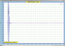
This in a screenshot from SoundEasy impulse. The connection is left channel balanced output connected to both channel input using a short split wire assembly. Left input channel impulse is used as reference to eliminate sound card effects from measurements. The right channel is the data channel which is shown in the lower amplified x8 impulse. As you can see, the right channel has quite some noise.
I will show an issue in the frequency plot in another post.
This looks like something is wrong either with your wiring or the processing in the software. Since both channels receive the same signal, the deconvolution of the two input signals from each other should give a perfect impulse. You're seeing quite a lot of ringing.
Can you do the measurement without the split wire? Use one wire from left-out to left-in, and one wire from right-out to right-in?
Can you do the measurement without using one channel as the reference for the other (i.e., without deconvolution of the two channels)?
Last edited:
- Home
- Design & Build
- Equipment & Tools
- DIY Audio Analyzer with AK5397/AK5394A and AK4490