I have questioned the horizontal effect mass of Kuzma airline arm many times. They used to state the horizontal effect mass, which is equal to the total mass of the moving carriage, was 80 grams. I think it is impossible to do that. Now, they don't state the horizontal effect mass on their website, but vertical effective mass, 13 g, only.
Update, Jim. Lot of stuff happening this year, so didn't get around to the mod you suggested until now: short vertical loop of 1/32" tygon replacing the 1mm hanging snake. Notable improvement in tracking - now the most challenging record cut I have (Power and Glory, M&K records, Organ solos, bass tremolo) has a 1/2 second of 'burps', which beats 2 x 2 seconds of hash. And that's it: 1/2 second of imperfect tracking across, I suspect, the whole record collection.
Thanks!
Thanks!
Great! I am glad that you made improvements.Update, Jim. Lot of stuff happening this year, so didn't get around to the mod you suggested until now: short vertical loop of 1/32" tygon replacing the 1mm hanging snake. Notable improvement in tracking - now the most challenging record cut I have (Power and Glory, M&K records, Organ solos, bass tremolo) has a 1/2 second of 'burps', which beats 2 x 2 seconds of hash. And that's it: 1/2 second of imperfect tracking across, I suspect, the whole record collection.
Thanks!
Hi Michael,
There is no skating force for the linear arm so you don't need an anti-skating device at all. The level of the shaft on my air-bearing arm is always in perfect condition. I use the tonearm cueing device to lift the arm up and let it down naturally many times to see if the air-bearing moves sideways. If the air-bearing doesn't move sideways, it means the shaft is perfectly leveled. If the air-bearing moves sideways, you need to adjust the level of the shaft.
On some mechanical linear arms, some people make the rail tilted in order to reduce the friction of the rail. For the air-bearing arms, there is no friction. You don't need to do that.
Jim
On some mechanical linear arms, some people make the rail tilted in order to reduce the friction of the rail. For the air-bearing arms, there is no friction. You don't need to do that.
Jim
Hi Jim, I have more questions
Why do you write that the arm should be attached to the bearing sleeve as high as possible? Does it seem more stable when the hand tube is at the bottom, or is your conclusion based on the fact that the center of the bearing should be at the level of the record?
And what advice would you give about the position of the counterweight?
Have you been able to measure vibrations at the air bearing itself?
Michael.
Michael,
I have the feeling that if the arm wand is mounted on the top half of the air bearing, it may cause less reaction force from the bearing. It isn't ideal to mount the arm wand under the air bearing. I realized that by studying the Kuzma airline arm. The arm wand should be mounted at least on the center of the air bearing or above.
The ideal position to mount the counterweight is the center line of the air bearing. Both center lines of the counterweight and the air bearing should be lined up for optimal performance.
It is difficult to measure the vibrations on the air bearing itself since the wire of the measuring device, such as a mic, may interfere with the movements of the air bearing. If there is a track with a closed loop, I may be able to do it since the air bearing won't move horizontally. In any case, even if I can measure it, I don't see the meaning of such measurements. The vibrations will transmit to the headshell and the air-bearing for sure. It is just the same as regular pivot arms. I measured the vibrations after the air bearing in order to understand the damping effect of air film within the air bearing in order to answer the criticism that the air bearing arms are not mechanically grounded.
Jim
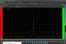
I understand it. However, it may be very difficult to find what causes these side bands.If you zoom in on the 300Hz fundamental there are a couple of sidebands visible at about -50dB if you want to improve the arm further find out what is causing these and you will hear an improvement in clarity. If you look at the plots in my post #4836 you can see the sidebands at 8.5Hz -47dB. These were caused by the OEM CW and its dynamic damping, basically decoupled CW. I made a new CW and stub that rigidly locked and the sidebands just about disappeared.
I also used my oscilloscope to see the waveforms of this 300 Hz track. In my air-bearing arm thread, I tested the trackability of my air-bearing arms by using different test LP and different waveforms. They looked pretty good though. But for this 300 Hz waveform, it doesn't look too good. Maybe it is time to roll up the sleeves again. But at this moment, I don't have a clue where to start with.
Warrjon,
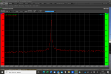
I also run the same 300 Hz without RIAA. Since I don't have a microphone preamp to connect the oscilloscope, I had to use a USB audio interface with a PC. I recorded the signal in Adobe Audition. Here is the result. It doesn't look too good either.

This is frequency analysis.

I have no idea what causes this. It probably will take a while to find out the reason. I understand that most commercial tonearms companies don't publish such test results. But I will try to solve this imperfection.
Jim
I also run the same 300 Hz without RIAA. Since I don't have a microphone preamp to connect the oscilloscope, I had to use a USB audio interface with a PC. I recorded the signal in Adobe Audition. Here is the result. It doesn't look too good either.
This is frequency analysis.
I have no idea what causes this. It probably will take a while to find out the reason. I understand that most commercial tonearms companies don't publish such test results. But I will try to solve this imperfection.
Jim
Last edited:
In the meantime, I got a mechanic stethoscope and really like it. I listened to these spots on my air-bearing arm.
It is no question. The sound level is the loudest at spot 1. The sound level at spot 7 is the 2nd loudest. This indicates that the center clamp is important. Then, the sound level at spot 2 is the 3rd. The sound levels at all other spots are almost the same and almost inaudible.
It is no question. The sound level is the loudest at spot 1. The sound level at spot 7 is the 2nd loudest. This indicates that the center clamp is important. Then, the sound level at spot 2 is the 3rd. The sound levels at all other spots are almost the same and almost inaudible.
Warrjon,
I also tried a 315 Hz 12 dB track from The Ultimate Analogue Test LP. It doesn't look so bad. The 315 Hz is up to 12 dB. This is the screen capture of the 315 Hz wave at 12 dB. Again, it has no IRAA. It may be smoothed out under IRAA.

The 300 Hz from HiFi News Test LP is 15 dB. The +3 dB makes the cartridge goes crazy.
Jim
I also tried a 315 Hz 12 dB track from The Ultimate Analogue Test LP. It doesn't look so bad. The 315 Hz is up to 12 dB. This is the screen capture of the 315 Hz wave at 12 dB. Again, it has no IRAA. It may be smoothed out under IRAA.
The 300 Hz from HiFi News Test LP is 15 dB. The +3 dB makes the cartridge goes crazy.
Jim
In terms of indicating good coupling (if this is desirable) the path between 7 and 1 would seem to be expected to be at similar levels. Also finding a way to compare 1 with the moving part of the air bearing, would be very educational. Although I don't use an air bearing i have a similar relative position of the lift mechanism which allowed me to briefly apply the stethoscope to the carriage by guiding it from the fixed part of the lift bar. Subjectively the mobile side on the carriage was the loudest and the fixed rail side 2/3-3/4 of that level, seeming to me to indicate good coupling.In the meantime, I got a mechanic stethoscope and really like it. I listened to these spots on my air-bearing arm.
View attachment 1106290
It is no question. The sound level is the loudest at spot 1. The sound level at spot 7 is the 2nd loudest. This indicates that the center clamp is important. Then, the sound level at spot 2 is the 3rd. The sound levels at all other spots are almost the same and almost inaudible.
I am afraid to let the probe touch the moving air-bearing. The risk may not be worth taking. Anyway, the energy from the cartridge will be certainly transferred to the headshell and moving part. For my air-bearing arm, there is no arm wand. So, detecting if the energy will be transferred through air film is meaningful. I understand if I know the sound level on the moving air-bearing, I can compare the level on the shaft. However, as I said before, it is too risky to do that. Even if I can find a safe way to listen to the air-bearing, it still involves uncertainty because I can't quantitate the level of sound.In terms of indicating good coupling (if this is desirable) the path between 7 and 1 would seem to be expected to be at similar levels. Also finding a way to compare 1 with the moving part of the air bearing, would be very educational. Although I don't use an air bearing i have a similar relative position of the lift mechanism which allowed me to briefly apply the stethoscope to the carriage by guiding it from the fixed part of the lift bar. Subjectively the mobile side on the carriage was the loudest and the fixed rail side 2/3-3/4 of that level, seeming to me to indicate good coupling.
Warrjon,
I also tried a 315 Hz 12 dB track from The Ultimate Analogue Test LP. It doesn't look so bad. The 315 Hz is up to 12 dB. This is the screen capture of the 315 Hz wave at 12 dB. Again, it has no IRAA. It may be smoothed out under IRAA.
The 300 Hz from HiFi News Test LP is 15 dB. The +3 dB makes the cartridge goes crazy.
Jim
There is still some mistracking there. Something to try is to change the COG of the carriage this could be done by changing the CW vertical position.
In a LTA that doesn't pivot vertical and horizontal inertia is different. What happens as the arm tracks eccentricity is the arm can move vertically as a result of the side forces, it takes less force to move vertically so the stylus can ride up the groove wall which is what I suspect is happening in the 300Hz 15dB track.
I used CBS test record to test the traceability today.
First, I did a square wave test. The result isn't perfect, but ok.

On the test LP, there is a 300 Hz track starting from +6 dB to +18 dB. The arm tracks the wave fairly well up to +15 dB. It was getting worse at +18 dB. Here is a screenshot at +15 dB.

I may try to rearrange the counterweight to see if it makes any difference later on. It will be nice if I can see a trace of the same track for other well-designed arms, so I compare them with mine. I guess commercial tonearms may never publish such test results.
First, I did a square wave test. The result isn't perfect, but ok.
On the test LP, there is a 300 Hz track starting from +6 dB to +18 dB. The arm tracks the wave fairly well up to +15 dB. It was getting worse at +18 dB. Here is a screenshot at +15 dB.
I may try to rearrange the counterweight to see if it makes any difference later on. It will be nice if I can see a trace of the same track for other well-designed arms, so I compare them with mine. I guess commercial tonearms may never publish such test results.

I may try to rearrange the counterweight to see if it makes any difference later on. It will be nice if I can see a trace of the same track for other well-designed arms, so I compare them with mine. I guess commercial tonearms may never publish such test results.
I have the HFN test LP so I'll do this for you tomorrow.
After some work on the plinth below my TT and TA they are now effectively much better coupled so that the path from the stylus to the pivot is as rigid as possible.I am afraid to let the probe touch the moving air-bearing. The risk may not be worth taking. Anyway, the energy from the cartridge will be certainly transferred to the headshell and moving part. For my air-bearing arm, there is no arm wand. So, detecting if the energy will be transferred through air film is meaningful. I understand if I know the sound level on the moving air-bearing, I can compare the level on the shaft. However, as I said before, it is too risky to do that. Even if I can find a safe way to listen to the air-bearing, it still involves uncertainty because I can't quantitate the level of sound.
I measured before I started this work and after, here attached are the measurements. the slightly "sharper" spike is due to better motor mounting which I did at the same time and the other channel showing the crosstalk is just a difference in how I set the measurement.
A worthwhile improvement in my opinion.
M
Attachments
Warrjon,
It is all right. Take your time.
I tested the tracking ability of my 1" air-bearing arm today again. The tracks are from CBS Test Record because I realized that there are two groups of tracks. One group is lateral and another group is vertical. Here are the results. The vertical trackings seem all fine.
Square Wave

300 Hz lateral 6 dB

300 Hz Lateral 9 dB

300 Hz Lateral 12 dB

300 Hz Lateral 15 dB

300 Hz Vertical 6 dB

300 Hz Vertical 9 dB

300 Hz Vertical 12 dB

From the test results, the mistracking happens in lateral tracking. It is understandable. The results also indicate that at 15 dB, the arm tacks one channel correctly the meantimes mistracks the other channel.
Jim
It is all right. Take your time.
I tested the tracking ability of my 1" air-bearing arm today again. The tracks are from CBS Test Record because I realized that there are two groups of tracks. One group is lateral and another group is vertical. Here are the results. The vertical trackings seem all fine.
Square Wave
300 Hz lateral 6 dB
300 Hz Lateral 9 dB
300 Hz Lateral 12 dB
300 Hz Lateral 15 dB
300 Hz Vertical 6 dB
300 Hz Vertical 9 dB
300 Hz Vertical 12 dB
From the test results, the mistracking happens in lateral tracking. It is understandable. The results also indicate that at 15 dB, the arm tacks one channel correctly the meantimes mistracks the other channel.
Jim
- Home
- Source & Line
- Analogue Source
- DIY Air Bearing Linear Arm