It is a very good desire, but unfortunately nobody invented yet neither anti-tube nor anti-transistor... Without them all means will lead to use the shortest part of a whole transfer characteristic, even NFB does that... It inevitably leads to one conclusion: the cleaner sound you want, the more you pay to a company who supplies you an electric power...
Thanks for the WE92a link Aerius, and thanks for the patent link John.
The Kreer patent is pretty hard reading, but here is my take on it.
Oh, by the way, does anyone have a copy or link to the Bell Systems paper mentioned in the patent:
"Modulation in vacuum tubes used as amplifiers" by E. Peterson and H. P. Evans, published in the Bell Systems Technical Journal for July, 1927. "
OK, the patent... Very difficult to understand the real mechanisms as written up with partial derivatives. But I think I see what they are driving at. They deal with the triode and come up with two complicated factors alpha and - beta for each order of harmonic generation. (these most likely have to do with the 3/2 power law for the g1 and similarly for the plate circuit. The grid operates unencumbered by loading, at least in A1 mode, but the plate operates with a load on it. Without this loading, ie CCS loading, the two 3/2 law effects track each other and we get a nice clean Mu gain. But with loading on the plate they don't, and so harmonics are generated by the plate component.)
They surmise that one component is generally positive and that the other is modifiable by altering load impedance for whatever harmonic. Because the odd harmonics all cause a variation of common mode plate current, putting a common mode resistance in the plate circuit can modify the impedance seen by those harmonics, and so can be used to match up alpha -beta to give a zero or null result. Hence we get Fig. 1 with a resistor 7 in the B+ lead.
Unfortunately, a different value of R 7 is likely needed for nulling each harmonic, but since they all are likely positive values, selecting a null with a pot for one harmonic is likely to at least reduce the other odd harmonics too. Also, the optimum value of R 7 for null changes with signal amplitude due to plate resistance dropping. (I think the common mode R 7 can be viewed as a means of unloading the plate circuit for the odd harmonics and restoring the similar 3/2 power rules between grid and plate circuits for these harmonics. Why it doesn't require a CCS is a mystery to me yet, but may have to do with the fact that the grid, being closer to the cathode, has more distortion factors inherent in its operation, like Island effect. This would lead to leaving some finite common mode load on the plates to match up distortions with the grids then. )
The patent also mentions that for A2 grid operation (grid current), that common mode resistors must be used in both the input circuit as well as the plate circuit to balance the alpha and beta factors for a null.
Figure 3 is hardly described, and at first glance looks most similar to the cross coupled feedback design. It uses a second order modulator ( still have to look that one up, but I guess it is something like a bridge rectifier). But here the similarity ends. The modulator takes as input the differential input drive signal and derives a single ended voltage to apply in series with the common mode B+ plate supply. The intention here is for the modulator to derive the same voltage drop that the previous common mode resistor 7 would have generated, thus saving power in the B+ supply. Fat chance. This scheme seems a little impractical.
Figure 4 is an approach for a single ended amplifier. It uses tuned circuits to modify plate load impedances for harmonics. This seems likely to have a very limited bandpass to me.
So my conclusion is that while the cross coupled scheme makes use of the same common mode plate current for monitoring odd harmonics, it does its compensation or nulling of harmonics by an entirely different means. The P-P driver circuit is used as a complementary gain modulator for the output tube's grid drives. The common mode output plate current being used to control its gain via tail current modulation.
Until someone builds and tests it with a spectrum analyzer, I couldn't say whether it does better or not at nulling all the odd harmonics than the Kreer patent. But my suspicion is that it is better.
My guess is that if it does work broadband, then it is probably written up as some op. amp. linearization patent already, since it looks suspiciously similar to some op. amp. internal differential circuits. And there are a lot of linearization patents and secret linearizer schemes around for op. amps.
Don
Hmmm... By the way, the cross coupled harmonic neutralizer scheme could be classified as a non-linear feedback scheme (well the common mode part, since it modulates forward gain by a multiplier)
Seems to me that Jan Didden (Janneman) was interested in this kind of thing.
Jan, calling Janneman....
Don
Seems to me that Jan Didden (Janneman) was interested in this kind of thing.
Jan, calling Janneman....
Don
Hi Pete,
Thanks for jumping in and explaining your circuit.
It makes sense to me now
Thanks for jumping in and explaining your circuit.
It makes sense to me now
pmillett said:
I didn't realize senile dementia can set in as early as your 40's... [/QUOTE
Hmm.....senile dementia?
I'm 47 and forgetting things.......hmmm
I'll make room for some real contribution to the topic now
Bye
smoking-amp said:Hmmm... By the way, the cross coupled harmonic neutralizer scheme could be classified as a non-linear feedback scheme (well the common mode part, since it modulates forward gain by a multiplier)
Seems to me that Jan Didden (Janneman) was interested in this kind of thing.
Jan, calling Janneman....
Don
Hello Donald,
Thanks for the heads-up, hadn't seen this thread yet. I'm not really a tube guy but at first glance your scheme reminded me of a development in solid state by Nelson Pass. I believe he calls it super symmetry (su-sy). Cross-coupled common mode feedback to lower odd order harmonics. I need to dig in deeper but maybe someone here is also familiar with the comcept?
http://www.passlabs.com/downloads/articles/susy.pdf
Jan Didden
Hi Jan,
Thanks for the lead on NP's Su-sy, I'll look into it.
I also just noticed that the HK Citation II has almost exactly this neutralizer circuit in it too. Cross-coupled plate feedbacks to a resistive tail loaded LTP (12BY7s) driver. It looks like it operates to about 30W in class A. The fast 12BY7A vertical amp tubes were unusual for an audio amplifier at the time, but are exactly what one would choose for a fast local error correcting loop needed to fix harmonics. Now I wonder if the tail resistance was chosen while looking at a spectrum analyzer.
Don
pmillett said:
Geesh, I forgot all about that one. I didn't realize senile dementia can set in as early as your 40's...
It might be due to a different, but common disorder called CRS. It's a chronic progressive condition, and as the condition worsens the change is indicated by changing the emphasis progressively, like so: It goes from Crs, to cRs, then crS. Technically I think it's an acronym for Can't - Remember - ah, er, well, Stuff.
Sheldon
Well, I read through Nelson's white paper on Su-sy and also looked at his patent 5,376,899. The figure 1 design appears to use the same common mode feedback principle, although it is in a modified form due to a folded cascode and P-channel output devices.
The signal inversion from the folding removes the requirement for cross coupling the output drains (plates) to the input LTP gates (grids). Odd harmonic currents still cause a common mode voltage feedback that changes the gain of the input LTP to effect gain correction if the tail resistance is set correctly.
The references in the patent do not seem to give any indication of an earlier patent with tubes or cross coupling (using all N-channel devices). But since the Citation II seems to use the Cross-coupled common mode feedback scheme, I think there must be some earlier patent or technical journal article. ???
I searched the patent office for Hegeman (Citation II) but found no patents.
The figure 2 thru 4 amplifiers in Nelson's patent do NOT effect common mode feedback error correction of odd harmonics in my opinion. This is because the totem pole outputs used do not produce a common mode voltage shift due to odd harmonics.
The patent itself does not even mention the common mode error correction effect. It appears to base all performance improvements on the cross resistor #40 (fig. 1) cross feeding errors between amplifier sides. But this is in reality nothing more than an ordinary differential pair.
Could it be that the common mode feedback, odd harmonic cancellation scheme has never been understood? Simply accidentally incorporated into designs.
Don
Big Oops!
I just noticed that the polarity of the common mode feedback in Nelson's figure 1 amplifier is the wrong way to effect common mode error correction.
Simple analysis, figure 1:
Let's say Mosfet #30 is giving too much gain at some point (it's conduction hence being in excess of the corresponding drop in conduction of the opposit Mosfet #31)
Out- then increases positively, pulling up the gate of Mosfet #20 thru feedback resistor #36. Now the conventional NFDBK thru Mosfet #20 and back to Mosfet #30 IS correct.
BUT, the positive common mode increase of current thru resistors #42 and #43 increases the gain of the differential pair #20 & #21 slightly (due to increased gm), and this is the wrong response to correct the increased gain of output Mosfet #30.
(It needs to decrease in gain so as to correct the original gain increase of #30)
So it appears that one must still use a circuit topology that cross couples the feedbacks from the plates (or drains) back to the grids (or gates) to get common mode correction of odd harmonics.
So it would appear that the NP patent completely misses the common mode odd harmonic correction scheme.
Sorry Nelson!
Don
Optimising the Cross Coupled Common Mode FDBK Harmonic Neutralizer
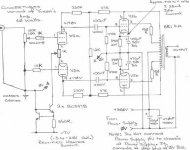
I have attached an improved schematic for carrying out the cross coupled common mode FDBK distortion neutralizer scheme.
Since the common mode current sampled signal from the outputs is relatively small (unless we include some more Rcm, we could try say the optimum 3rd harmonic value from the Bell Labs/Kreer patent), we need to optimize the driver stage design for maximum sensitivity to it. So forget about screen feedbacks. Back to using g1.
Lowering the value of R2 increases the sensitivity to the common mode signal, but too low a value here will cause the driver stage to generate excessive odd harmonics itself. So the plate feedbacks, R10, are attenuated with a cross resistor, R11, that does not attenuate common mode signals, only differential ones. Grid 1 bias resistors R1 will want to be as large as we can get away with.
Degeneration resistors like R4, while tempting for linearizing the driver, would ruin common mode sensitivity, so they are out. If pentodes are used for the V1,V2 drivers, we may want to include plate feedbacks R9 for linearizing them. It turns out that for a single stage, no cross coupling is needed, and further, that this has the correct polarity sense for common mode error correction of the driver stage as well.
Since g1 of the drivers has some small input capacitance, we might shunt the R9 and R10 feedback resistors with appropriate small sized pF caps to preserve the attenuation ratios at very high frequencies. This is a high speed corrector after all, lets keep the bandwidth up.
As long as the outputs are not drawing class A2 grid current, there would seem to be no need for R7, so R7 is out. R8,C2 is just for biasing, any of the usual schemes can be substituted here.
Similarly, biasing for the driver stage can be any of the usual schemes, just keep common mode resistance of the grids to ground high as possible without getting into grid leak problems.
R2 is a pot for adjusting common mode correction gain while looking at a spectrum analyzer view of a test signal into a nominal load resistance RL. Adjust until happy.
The Vin grid drive points indicated are rather low impedance due to the feedbacks, so are really more like Iin points from the pre-stage/splitter. The C3 caps are situated to do triple duty for both feedbacks as well as input DC isolation.
You might notice now that the resulting schematic is stunningly close to the Citation II except for UL mode pentode outputs. Is this just coincidence?
Don
Attachments
I may be way off here but does the "Baby Huey" circuit have some of this cross coupled harmonic distortion in it's design?
At our Irish meet, a while ago, this amp was agreed as second best. Considering it was built using a modified Roger Cadet II with a so-so pre-amp & small OPT - it is testament to this circuit!
At our Irish meet, a while ago, this amp was agreed as second best. Considering it was built using a modified Roger Cadet II with a so-so pre-amp & small OPT - it is testament to this circuit!
Attachments
jkeny:
"I may be way off here but does the "Baby Huey" circuit have some of this cross coupled harmonic distortion in it's design?"
Well, as presently configured, no. This is single stage shunt or partial feedback. You can get a small amount of common mode feedback with a single stage by putting a tail resistor in the outputs cathodes in this case, but the B+ power loss would not be worth it or the increase in output impedance.
To get sufficient common mode gain, one needs to do two stage shunt feedback by going further back to the driver grids, which then needs the feedbacks crossed because of the signal inversion in the drivers. Also an adjustable resistance for a tail instead of the current source presently used.
The feedback resistances will need adjusting to allow more closed loop gain then too. Also, the driver input grids will then have a low impedance due to the feedbacks, so it will need another gain stage in front of the drivers to buffer the input.
This then becomes essentially the configuration Thorsten (Kuei Yang Wang) was strongly promoting, but with a tail resistor required instead of a CCS so as to get common mode non-rejection or gain.
Don
Would this principle work?
See att.
The common mode signal on Rk2 that originates from the penthodes will feedback trough Cf to the cathodes of the driver and thus form a common mode neutralizer.....
As a bonus the partial feedback can still work.......... or does it?
See att.
The common mode signal on Rk2 that originates from the penthodes will feedback trough Cf to the cathodes of the driver and thus form a common mode neutralizer.....
As a bonus the partial feedback can still work.......... or does it?
Attachments
Markanica:
"Would this principle work?"
Interesting, but I think it may have a problem, maybe quite solvable.
With the original cross coupled scheme, an unneeded increase in an output tube conduction causes the common mode voltage of the drivers grids to drop, reducing their current and thereby the lowered gain in the drivers to compensate.
In your scheme, the Rk2 voltage would increase, then be conveyed to the driver cathodes by Cf, and lower the current in the drivers as desired. But I think Cf and Rk2 will place a very low impedance on the tail of the drivers, causing them to generate excessive odd harmonics themselves. We would like to keep the driver tail resistance as high as possible but still get sufficient common mode feedback effect.
I would suggest that the Rk2 voltage be used to control the current level of a current source in the tail of the drivers. (or alternatively control a current source dumping into the driver tail resistor.) This would keep the driver tail impedance up for low distortion in the driver itself, but may give exceptional control of the common mode gain effect. I think this may be on to something useful.
Don
Re: Optimising the Cross Coupled Common Mode FDBK Harmonic Neutralizer
Don -
So it seems like a natural to drive this node from the plate of another pentode, yes?
I'd like to try this on a breadboard and see how it works. Unfortunately I'm travelling for the next few weeks...
Pete
The Vin grid drive points indicated are rather low impedance due to the feedbacks, so are really more like Iin points from the pre-stage/splitter.
Don -
So it seems like a natural to drive this node from the plate of another pentode, yes?
I'd like to try this on a breadboard and see how it works. Unfortunately I'm travelling for the next few weeks...
Pete
Hi Pete,
Yes, a pentode would seem a good fit for the input stage. Looks like the Citation II schematic used one too. I guess we are re-inventing it.
Mark,
I have attached a possible scheme to use the output cathode current to control a CCS in the drivers. Rather hurriedly put together though, it definately looks dangerous for possible bias runaway for the outputs. Needs some serious simulation effort and more thought I think.
Don
Attachments
Now we're cookin'! See attached.
Q2 could be a Jfet or Ixys 10m45 or Dn2540 or Mosfet FQP1N50 or ... Pentode!
The Common Mode loop will be much faster with just one device in grounded gate or grounded grid this way. And the high impedance CCS tail on the drivers will keep them nice and linear.
I haven't bothered to draw in the cross-coupled feedbacks since they are no longer part of the common mode corrector loop. Their common mode voltage on the driver grids no longer has any effect due to the high impedance CCS in the tail. Common mode correction is done directly by current sensing of the output tube cathodes (Rsense) controlling the current output of the driver CCS (Q2, Riset). Adjust Rsense for the common mode correction loop gain control.
I would still recommend using the cross coupled plate feedbacks to the driver grids (or driver screen grids now are OK) though for the conventional local NFDBK.
Don
Attachments
smoking-amp said:Now we're cookin'!
") Nice
Nicesee att.
Now it becomes almost the same flavor as in pmillet's EL802 scheme
I'd like the partial feedback as in "baby huey" to stay in
what do you think
Attachments
Hi Mark,
The common mode signal is inverted between the output plates and the cathodes, so the the rk2 pickoff has the wrong CM signal polarity to apply to the driver grids. (ie, we were using the CM plate signals back to the driver grids before, so the CM cathode signal to the grids will be wrong.)
Quick check: If an output is supplying too much gain, the current thru rk2 will increase, this works its way back thru Cf and the input xfmr to the driver grids to raise CM conduction there. Increased tail current then increases driver gain. But we need a complementary decrease in driver gain to compensate the increase of the output tube. Back to drawing board.
Assuming the schematic in post #31 by jkeny is a clone of the "Baby Huey", it would seem a simple mod to convert the CCS to work like the scheme in post #37 above.
Talk about senile dementia and "CRS", I just remembered this post from wayback (post #791):
http://www.diyaudio.com/forums/showthread.php?postid=537205#post537205
I had the very same idea of modulating the tail current of a differential LTP pair to compensate gain. I just lacked a decent control signal then for controlling it. Now we have the near perfect control signal, Common Mode output current. (Well, it only works for class A operation)
Don
smoking-amp said:Hi Mark,
The common mode signal is inverted between the output plates and the cathodes, so the the rk2 pickoff has the wrong CM signal polarity to apply to the driver grids.
I'm not sure I follow you here. Let's suppose the output stage creates only 2nd and 3rd order harmonics. The common mode signal will consist of the 2nd order harmonics as well as some DC. That is, if we drive the amp with a 1kHz sine wave, then the common mode signal will be 2kHz and will have shifted slightly in DC level relative to the zero signal case.
In many implementations (including those by WE) the CM signal is cap coupled back to somewhere earlier in the amp - perhaps the grids of the output tubes. The cap coupling means that only the 2nd order harmonics are present without the DC shift. So my question is this: how does flipping the phase (180 degrees) of a 2kHz signal make any difference relative to the 1kHz signal that it was born from?
The early WE (Bell Labs) guys didn't seem to think that the DC shift was part of the mechanism at work here. It might have another benefit, namely linearizing the gain as a function of signal level, but that, I think (they thought) is not part of the harmonic equalizing effect.
-------------------------------------------------------
I have read through Don's earlier post describing the mechanism (thank you), but I admit that I still do not understand how injecting a 2nd order harmonic into the grids of a PP stage cancels generated 3rd order. The explanations that I have heard previous to this thread use multiplication as a byproduct of nonlinear mixing: adding the 2kHz signal to the 1kHz signal results in 3kHz and 1kHz byproducts. The 1kHz component either adds or subtracts from the fundamental while the 3kHz hopefully subtracts from the generated 3rd order harmonic distortion.
Perhaps all of that is rolled into the explanation presented here. It could easily be that the multiplication is just a good way of expressing it mathematically but not very helpful in conceptualizing what's going on... but I'm just too dense to see it.

-- Dave
- Status
- This old topic is closed. If you want to reopen this topic, contact a moderator using the "Report Post" button.
- Home
- Amplifiers
- Tubes / Valves
- Distortion Neutralizer for Odd Harmonics