.
The simplified Wurcer 990 I post in #1692 has excellent performance. On fas42's more stringent 100x 20kHz 20Vpp 600R test in #1694, its actually better than Guru Wurcer's more complex supa dupa circuit.
2nd -101.7dB 3rd -102.8dB Simplified 990
2nd -89.9dB 3rd -89.3dB Wurcer SupaDupa
ricardo 'wannabe a SPICE guru' lee
Just stick a 1N914 in (an oversite). That circuit is a fine option since it can do the 75 Ohm drive. Samuel Groner bases a few on the JE990-ish circuit but this one does not need inductors.
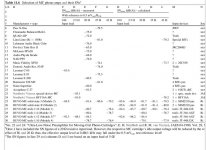
The 0.28nV/rtHz version runs 3mA total with 2 of the Hitachi devices. More current doesn't help which tends to confirm the rbb. The 2 'commercial' versions didn't use more current cos there weren't any MC amps at that time that were quieter with real MC cartridges .. even with my non-optimal noise matching. Description is in README.doc[/edit]
That works. As an historical point Nordholt and Van Vierzen ran a custom IC for the same Ortophon cart in 1980 (rbb = 1.4 Ohm). I have probably the only two left in existance. Your complimentary version is far more satisfying and simple (they used a HUGE coupling cap) even though they might have shaved a few tenths of a nanovolt.
Attachments
Last edited:
I'm getting somewhat worse figures: with perfect matching of 3 FETs and just one out by 10% on Idss the drift is over 50uV, if only the FETs are subject to temperature change. The rest of the circuit offsets the drift to some degree, with the bipolars I've got. If the single mismatch is 17% (the first one I tried) the drift is 100uV ...With default values I found the worst case drift AFTER trimming the offset back to zero was about 20uV/C for both pairs of FET's having a 10% mismatch of Idss (combined in the worst way).
Will be interesting to see what the real devices do ...
Frank
Some good news, hopefully ... I mentioned on another thread about using an NTC thermistor for thermal feedback, so tried this as a simple alternative in the sim: the drift caused by a single mismatched FET in the previous post was compensated for, by including the thermistor in a balance of resistors of a current source and managed fairly easily to restrict drift to only 15mV at x100 gain in the range 27 to 57 degC. This equates to a drift of 5uV/degC ...
Frank
Frank
Last edited:
second the motion
I'll second that motion.
i'm all for the complex version myself, i'll try both, but its always good to have options and I want to offer my encouragement for the development of this fresh circuit.
I'll second that motion.
Thermistor offsets drift

Shouldnt we prototype the thing and learn the true story on what it 'really', actually does and then see if such is needed or other way? Especially with conflicting sim results...
git er done.
Some good news, hopefully ... I mentioned on another thread about using an NTC thermistor for thermal feedback, so tried this as a simple alternative in the sim: the drift caused by a single mismatched FET in the previous post was compensated for, by including the thermistor in a balance of resistors of a current source and managed fairly easily to restrict drift to only 15mV at x100 gain in the range 27 to 57 degC. This equates to a drift of 5uV/degC ...
Frank
Shouldnt we prototype the thing and learn the true story on what it 'really', actually does and then see if such is needed or other way? Especially with conflicting sim results...
git er done.
Last edited:
PLEASE let's get beyond SIM! We've talked it to death. How about a parts list with the latest additions for both the SWfetJE990 as well as the new SWOPA? It would be great to have a post with the most recent schematics in one post where we don't have to hunt through 179 pages. Thanks, Ray
PCB layout assistance?
Hello folks,
I am following this thread as a learning experience. Gives me a chance to learn some analog design techniques & LTSpice as well.
Since it is such a small PCB, I can offer my assistance to continue doing the PCB layout and provide the fab data when completed. No sense in duplicating a parallel effort, if someone else is doing it as well.
I did not get much feedback, when I posted my first attempt, maybe to early for this to be reviewed, that's okay. If you want me to continue, just let me know? If not, good luck with your design!!
Regards
Rick
Thanks Scott!Your complimentary version is far more satisfying and simple (they used a HUGE coupling cap) even though they might have shaved a few tenths of a nanovolt.
I gotta confess I originally took someone else's circuit, threw bits out and changed others to get SOTA performance. Just focussing on what's required for good sound and ignoring all Golden Pinnae considerations.
ricardo "whose head is now too big to get through the door" lee
JFET 990
.. unless Scott is suggesting putting it in some cunning spot instead of as just a clamp
Sam mentions this effect in his critique of Self's book but he dun offer a solution.
Here's a version which doesn't need the clamp and approaches Wurcer performance but I'm not 100% happy with overload. Still not sure what causes the stuff that needs the clamp in the original 990.
I've removed a complete gain stage and it still has supa dupa THD.
A new project needs to offer substantial benefits over tried & tested. Don't think SWfetJE990 is ready yet though if anyone has some JE990s they don't mind modding ... I now know it has the potential for SWOPA THD. Just need it to behave on yucky stuff like overload & PSR.
Gotta put back the i/p cascodes, look at PSR, do a cap vs CL gain chart bla bla ..
This is my first serious use of LTspice and I'm having fun finding out where it does (and does not) emulate real life.
Anyone know of a good tutorial on what da SPICE BJT & FET models mean?
Does that mean the clamp I'm looking for is truly Unobtainium?No signal voltage across this point. Richard is talking about the JFET JE990 which has clamps that do see the signal. In IC's we had to use PNP's that had no reverse EB breakdown.
1n914, other diodes & diode connected BJTs as clamps don't come close to Wurcer performance. Have to stop Early effect & Cob modulating the VAS input.Just stick a 1N914 in (an oversite). That circuit is a fine option since it can do the 75 Ohm drive. Samuel Groner bases a few on the JE990-ish circuit but this one does not need inductors.
.. unless Scott is suggesting putting it in some cunning spot instead of as just a clamp
Sam mentions this effect in his critique of Self's book but he dun offer a solution.
Here's a version which doesn't need the clamp and approaches Wurcer performance but I'm not 100% happy with overload. Still not sure what causes the stuff that needs the clamp in the original 990.
I've removed a complete gain stage and it still has supa dupa THD.
PLEASE let's get beyond SIM! We've talked it to death. How about a parts list with the latest additions for both the SWfetJE990 as well as the new SWOPA?
A new project needs to offer substantial benefits over tried & tested. Don't think SWfetJE990 is ready yet though if anyone has some JE990s they don't mind modding ... I now know it has the potential for SWOPA THD. Just need it to behave on yucky stuff like overload & PSR.
Gotta put back the i/p cascodes, look at PSR, do a cap vs CL gain chart bla bla ..
This is my first serious use of LTspice and I'm having fun finding out where it does (and does not) emulate real life.
Anyone know of a good tutorial on what da SPICE BJT & FET models mean?
Attachments
[snip] Still not sure what causes the stuff that needs the clamp in the original 990.
[snip]
Anyone know of a good tutorial on what da SPICE BJT & FET models mean?
The diode prevents the output of the stage from saturating on overloads. BJTs recover from saturation a little slowly, depending upon the device type.
Massobrio and Antognetti, Semiconductor Device Modeling with SPICE, 2nd ed., 0-07-134955-3 is cautiously recommended as I haven't read it yet, but it looks worthy. May be a teensy bit dated --- the copy I have is "A McGraw-Hill special reprint edition" and the original dates from 1993.
FWIW, I found that my BAV99s (possibly NXP) have weakly magnetic leads, maybe due to Kovar/Nickel plating. It's probably not an issue for output-side Baker clamps and similar, but may be an issue for input anti-parallel clamps due to increased EMI pickup. It probably pays to check everything with a magnet, including the BF862s....
Most component leads are weakly ferromagnetic. I used a permanent magnet to retrieve a tiddly-winked BF862 from the carpet just the other day. I was glad for the property then But to handle SMD you had better have completely non-magnetic tweezers or you will be very irritated.
But to handle SMD you had better have completely non-magnetic tweezers or you will be very irritated.It's amazing how wasteful breadboarding has become in our lab. No one wastes the time to pick up anything off the floor and always take a whole strip of unlabled SMD parts when they need only one or two. The piles of unidentifiable parts are everywhere.
My top pet peeve when I shared lab space at Harman was the guy who took whole containers of SM resistors of a given value and moved them to his bench, rather than extracting the few he needed and leaving the little box in the cabinet drawer. Although I will say that when you found a drawer missing a value, you knew where to go and look.
The second in line was the use of "standard values" of resistors whenever, rather than an adjacent E96 that would have worked as well. As a result there was always an irregular depletion of 1k and 10k, and the tech in charge of keeping things stocked hated ordering certain parts, especially resistors.
He also once told me that something he'd built for me (in this case using 5% carbon film) had 11k resistors instead of the specified 10k, since that value was obviously so close
 Yes, it wasn't terribly critical that time, and following my own philosophy perhaps I should have specified 11k to begin with, but the exposure of the innumeracy was disconcerting. Followed, a brief lecture on estimating ratios. Good thing I was nice most of the time.
I use a lot of #1 coin envelopes around here. Often, rather than discarding a part off of a board I will save it and label the envelope.I will volunteer to identify the next box of strips of unmarked foil resistors for you, i'm selfless that way, its just how I roll
The producers of Hoarders will probably be in touch soon.
I also bought one of those clever tweezer meters. They are not super-accurate but less prone to flipping the SM part across the room.
haha I so something similar, except I have a ring-binder full of them. I do the same with digikey, mouser etc packing materials (particularly DK), recycling snappies, handy size boxes and that awesome brown paper mesh packing/padding is good karma, of course I have far more than I will ever use. those who know the digikey packing regime will know what I mean....
most of my work is sent international mail, so its a legitimate thing to do, but.... i've lost nearly an entire room.
same with short lengths of silver solder (cardas and kester), UPOCC copper in PTFE, the extra different size strain reliefs from connectors, empty cardboard reels from sleeving and wire, manuals I will never read...
tweezer meters? you mean reverse tweezers that stay closed? if not, linky please?
I'm not worried about saturation.The diode prevents the output of the stage from saturating on overloads. BJTs recover from saturation a little slowly, depending upon the device type.
The red circles in noLatch.gif show the OPA coming out of -ve saturation. 280mV 20kHz i/p into 100x circuit with +/- 16V rails. Not a problem for audio as recovery is virtually instant.
Green circle in OL.gif shows what happens if you leave off the clamp diode on original FETje990. Something triggers on +ve overload.
Thanks Guru Brad. But this beach bum was hoping for a free internet tutorial.Massobrio and Antognetti, Semiconductor Device Modeling with SPICE, 2nd ed., 0-07-134955-3 is cautiously recommended as I haven't read it yet, but it looks worthy. May be a teensy bit dated --- the copy I have is "A McGraw-Hill special reprint edition" and the original dates from 1993.
Attachments
- Home
- Source & Line
- Analog Line Level
- Discrete Opamp Open Design