This circuit is shown here, and discussed close to the end of the Audio Xpress interview with Walt Jung
WaltsBlog
Probably off topic here, but worth a new thread in the right place...
yeah I know, seen it, thats why I mentioned it
") there is already a thread here
there is already a thread herewhich strangely hasnt gotten much attention, given the shunt anything, anytime, at any cost whether there is benefit or not trend that seems taking DIYA by storm. I just thought it might be interesting to bring it up so the 2 could be explored. if indeed we need very good regulation, it would seem to be pretty suitable for the voltages and currents involved.
but yes maybe keep conversation of the reg itself in the thread.
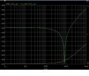
OK I was talking about the post #1380 circuit. Here's a plot of PSRR (at the output) at 20K vs source impedance when the feedback network is 1k,9k (20dB gain). Notice the suckout at exact source resistance match in the un-cascoded case.
This is with and without the J111 or depletion mode MOSFET cascode on just the two input devices. So without you need better supplies. The two devices I now would consider essential.
Does this make our results line up?
This is with and without the J111 or depletion mode MOSFET cascode on just the two input devices. So without you need better supplies. The two devices I now would consider essential.
Does this make our results line up?
Attachments
Last edited:
Apologies Brad - dadod's sim in post 1455 references the complementary version of the circuit in post 1397. His were both done at G=21.
G=1 does change it a bit but the cascodes appear to make all the difference.
And much like your post 1542 Scott, the pseudo complementary front end is better than the complementary version for PSRR. Looks just as flat in LTSpice, but even more optimistic for rejection.
Dave
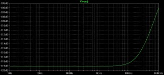
PSRR
This is what I'm getting when simulating Scott's BF862 circuit with the buffer.
I have also attached the schematic I'm using, showing how I do the PSRR simulation. Maybe I'm doing it wrong?
Stein
G=1 does change it a bit but the cascodes appear to make all the difference.
And much like your post 1542 Scott, the pseudo complementary front end is better than the complementary version for PSRR. Looks just as flat in LTSpice, but even more optimistic for rejection.
Dave
Attachments
OK I was talking about the post #1380 circuit. Here's a plot of PSRR (at the output) at 20K vs source impedance when the feedback network is 1k,9k (20dB gain). Notice the suckout at exact source resistance match in the un-cascoded case.
This is with and without the J111 or depletion mode MOSFET cascode on just the two input devices. So without you need better supplies. The two devices I now would consider essential.
Does this make our results line up?
I was just about to ask about the effects of impedance match at the two inputs, for which this confirms the importance.
I've hit a little snag. It seems the external power device models don't work well in my simulator. It looks like a quasi-sat issue since the dynamic base currents have impossibly fast discontinuities. They look fine in LTSPICE but that means I have to use a personal computer to verify any high power circuits.
Yes PLEASE!General appeal: could people please reference a post # when referring to a design? It would burden things unduly to attach the schematic each time, but at least we can use the number and go back and confirm what we're talking about.
Isn't this from #1380 which Scott has deprecated in favour of #1397 and also has missing traces?SW BF862 with buffer.pdf (34.6 KB, 20 views)
Isn't this a consequence of using big geometry FETs on the i/p LTP?OK I was talking about the post #1380 circuit. (duu.uuh!) Here's a plot of PSRR (at the output) at 20K vs source impedance when the feedback network is 1k,9k (20dB gain). Notice the suckout at exact source resistance match in the un-cascoded case.
This is with and without the J111 or depletion mode MOSFET cascode on just the two input devices. So without you need better supplies. The two devices I now would consider essential.
You have similar effects with BJT LTP i/ps but much smaller ... especially if you use NPNs. I found this in a low feedback Power Amp design.
I'd still like to know why we are using FET i/ps.
Yes PLEASE!
Isn't this from #1380 which Scott has deprecated in favour of #1397 and also has missing traces?
i/ps.
I just can't seem to stop confusing people. There are three circuits that simply display three common input stages. The rest of the circuit is the same. I had a problem with JPEG and noticed that the second one had all the connections intact, I hoped folks could connect the dots. My comment was just to point this out.
The #1380 circuit uses no hard to find parts and probably does everything needed. I need to add the cascodes and make a new definitive version. The second and third circuit have very high slew rates if that appeals to someone as important. Just trying to show how versitle some simple ideas can be.
Last edited:
I'd still like to know why we are using FET i/ps.
FET's simply have a much larger linear input range for the same gm (hence noise level). The GBW vs slew rate is also much more favorable with FET's.
Anyone have a fully corrected version of #1380 with missing traces re-instated? Maybe even an LTSpice model. It appears Scott is concentrating on developing this version.I just can't seem to stop confusing people. There are three circuits that simply display three common input stages. The rest of the circuit is the same. I had a problem with JPEG and noticed that the second one had all the connections intact, I hoped folks could connect the dots.
Also of #1397 please?
Those of us with small brains have difficulty with connect the dots.
OK, I'm doing a version of the n FET version in #1380 right now, for LTspice. Working, but some funnies with the bipolars so far; give me a chance to check a few things first ...
I'll be calling that version SW-OPAn, the other SW-OPAc, unless someone has a better thought ...
Frank
I'll be calling that version SW-OPAn, the other SW-OPAc, unless someone has a better thought ...
Frank
Last edited:
Using local degen -
For power amps and line level amps; Some jFEts have a pretty high Vp - several volts and low capacitance.
Adding local nfb/degeneration can pretty much take the Gm out of the picture and makes matching easier.
[I made it!! ... Its Sunday - sitting on the 15th floor in downtown Bangkok, Thailand at this time.]
-Thx -- RNM
If the circuit is from eg #1380, perhaps SW-OPA1380fas42 might be good.I'll be calling that version SW-OPAn, the other SW-OPAc, unless someone has a better thought ...
This would show who did the model too. And please put the information in the *.asc file as a text line too. And the date.
If the circuit is from eg #1380, perhaps SW-OPA1380fas42 might be good.
This would show who did the model too. And please put the information in the *.asc file as a text line too. And the date.
I think better is to put *.asc file together with the models file in one zip file. When a models are on the *.asc it's not easy to read, to many diffetent text screening the schematic.
dado
Definitely!I think better is to put *.asc file together with the models file in one zip file. When a models are on the *.asc it's not easy to read, to many different text screening the schematic.
But I was referring to simple info like
- who's circuit
- who did this SPICE file
- date when it was done/last edited
I agree it's a good idea to document as kgrlee suggested ... everyone has their own ways of doing things, and I tend to put everything on the one diagram, and scroll to the appropriate bits. One thing that has always bugged me with LTspice is that it keeps deciding what zoom level to show the schematic at, when I set up the views in the way to suit me, so I've worked out a couple of tricks to get around that ...
In the meantime, I'm waiting for Scott to post his next version, no point in adding to the confusion by introducing something which will be out of date in a few hours ...
Frank
In the meantime, I'm waiting for Scott to post his next version, no point in adding to the confusion by introducing something which will be out of date in a few hours ...
Frank
Latest schematic, I added input cascodes and tied the bias setting current surces together at the drains so only one cascode would be needed (for operation at high supply voltages). The two .1uF capacitors no longer seem to do anything (it could have been a simulation artifact) so they are gone. This should be fine gain of five and up, still looking at lower gains.
Cascodes are J111 or a depletion mode MOSFET as we discussed.
Cascodes are J111 or a depletion mode MOSFET as we discussed.
Attachments
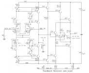
Latest schematic, I added input cascodes and tied the bias setting current surces together at the drains so only one cascode would be needed (for operation at high supply voltages). The two .1uF capacitors no longer seem to do anything (it could have been a simulation artifact) so they are gone. This should be fine gain of five and up, still looking at lower gains.
Cascodes are J111 or a depletion mode MOSFET as we discussed.
Hi Scot,
What are the NPN and PNP transistors?
- Home
- Source & Line
- Analog Line Level
- Discrete Opamp Open Design