The statement is made that in blind A/B testing the listeners noted the improvement in 30 seconds, which does not sound like only the effect of phase response.
Any idea how they controlled level matching? That's always my suspicion with rapid identification...
Joachim,
Thank you for the reference to the Noise and Vibration website. That looks like some very interesting information and I will spend some time on there reading about the many subject matters listed. I will also need to refresh my brain on some of the mathematics and learn some new things but I still think that it will provide some great information.
Steven
I know that almost everyone here has traces of analogfrontenditis antibodies running
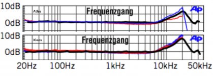
Boron (Kleos) and diamond coated Boron(Atlas),are selected as cantilever materials for to couple the tip to the motor most efficiently at higher audio frequencies.
If tip is excited (resonated?)at very high frequencies, these are transmitted to the motor with 4-6 times less attenuation compared to an aluminum cantilever. Lyras cantilevers are solid rods. The elastomer is not able to do any damping to these. In Atlas I read there is a double knife edge cantilever mounting, further reducing any damping action of the elastomer.
At the curves that Joachim posted, what is the black line?
(is it the “best fit” from the red( R ) and blue (L) lines-data points ?).
I see that red and blue lines stops a hair above 20KHz.
How does the black line slops down up to 30KHz?
There is not enough data in these graphs to show that red and blue also only peak at 20K. How can one tell from these graphs that they would not continue to climb past 20K (the linear slope of the blue line seems to be a data mistake)
The real form of these lines way past 20KHZ might give some clue as to what really happens and what one can do
.
Lowering the Ohms of the cartridge Rload (assuming preamplifier’s Rin is high) will increase the current through the coils and since V is analogous to modulation velocity (constant at high freq) will increase the power output of the generator thus increasing the mechanical load on the cantilever equally at all frequencies at least above ~2KHz.
The frequency variable - electrical (*) variable - in the circuit is the coil inductance. This should reduce the current progressively by increase of the frequency, thus mechanically unload the cantilever in the same fashion.
If the pre is a current to voltage converter, it’s low input impedance can efficiently convert the increased current of the coils to increased voltage and provide some damping as well, if the last one has any effect
(*) there is also the mass inertia of the moving system which affects the system in the opposite way to the electrical inductance
George
Attachments
Any idea how they controlled level matching? That's always my suspicion with rapid identification...
Yes, that's even more obvious and easy to discern, with louder almost always perceived as better unless there is something horribly wrong with the louder. I have no idea, although it may be in one of the papers on the website for van Maanen.
This is the one referred to by vanRaalte, it appears: http://www.temporalcoherence.nl/docs/MERK1980.pdf
Unfortunately Google translator says it is translating the site text at least, but winds up not doing anything!
Afterthought: most likely level matching is used, since the overdamped case involves some attentuation and by the louder is better argument would not be preferred. [4th edit:] Of course it may have wound up at a slightly higher level, unintentionally.
Second edit: I scanned through and didn't see listening test results, but I may have missed it --- [3rd edit] although at the very end there seems to be the assertion that it sounds better.
Last edited:
Where the "ground" is physically/electrically is another issue. Jneutron might be the one to have something on that.
In the grounding articles I've seen, like Whitlock's pin 1 stuff, only IR drop is considered. It is very important to consider the mutual coupling between circuits as a result of common elements. bcarso understands this quite well, he knows the 4 wire caps..
That sounds perfectly logical. Is that indeed the case? Somehow intuitively I can hardly imagine that tiny coil damping those mechanical vibrations - but my intuitions often are wrong.
Anybody has expertise about this?
jan
There will be mechanical damping as a result of the lowering impedance of the coil due to electrical loading.
The amount of mechanical damping will depend on the coupling coefficients, they define the stiffness that can be imparted on the moving system. I suspect it's not very much however. I do not have numbers for this however, I don't believe anybody really considers conversion efficiency of a cart.. So I'd venture a guess that the R/L of the coil with the external cap load will electrically dominate the system, coupling based damping is probably orders of magnitude below that.
jn
That was my guess too. So the cantilever will merrily ring away while the cart output is nicely smoothed.
Not sure what the consequences are, if any.
jan
In the grounding articles I've seen, like Whitlock's pin 1 stuff, only IR drop is considered. It is very important to consider the mutual coupling between circuits as a result of common elements. bcarso understands this quite well, he knows the 4 wire caps..
There will be mechanical damping as a result of the lowering impedance of the coil due to electrical loading.
The amount of mechanical damping will depend on the coupling coefficients, they define the stiffness that can be imparted on the moving system. I suspect it's not very much however. I do not have numbers for this however, I don't believe anybody really considers conversion efficiency of a cart.. So I'd venture a guess that the R/L of the coil with the external cap load will electrically dominate the system, coupling based damping is probably orders of magnitude below that.
jn
Whitlock does discuss the effects of unequal magnetic coupling between hot/neutral and the safety ground in conduit, and attributes most of the potential differences in safety grounds in different outlets to this effect. He's had skeptical electricians pull out the hot/neutral conductors and twist them together, then re-install. Sometimes it helps a lot.
With phono cartridges, I suppose one way to evaluate the mechanical/electrical coupling would be to drive the cartridge coils and look at the needle's displacement. Maybe a Keyence, if it's practical to use it on a spot that small. Of course this would be in free air, and the restoring force could be measured independently. The effect based on the real situation of the stylus being dragged through a groove is something else again. Surely someone has done this somewhere.
On the subject*, the notion of using the damping resistor to create the 75us tau led me to wonder how constant the cartridge inductance is with displacement. So I did a crude measurement on an old MM, a Shure M91ED. By moving the stylus from one extreme side to the other, within as close as I dared to the elastic limit, the inductance of ~700mH changed by about 1%. Of course such displacements would at most be seen on some tracking test at low frequencies, but there would be an intermodulation with higher frequency energy if present. I suspect here as well, any such would be small compared to other effects, such as the variable sensitivity with displacement at higher frequencies.
*and sorry further musings off topic --- maybe a moderator can move some of these to a new thread.
Whitlock does discuss the effects of unequal magnetic coupling between hot/neutral and the safety ground in conduit, and attributes most of the potential differences in safety grounds in different outlets to this effect. He's had skeptical electricians pull out the hot/neutral conductors and twist them together, then re-install. Sometimes it helps a lot.
Since the power company uses the earth as neutral for the hv transmission towers, earth as neutral along all the power paths, as well as at the houses in a residential system, there will be what is known as "stray current" actually running through the earth. In residential areas, this can be anywhere from zip to 5% of the total current of the neutral. While the power providers attempt to keep neutral currents zero, that never happens. This stray current produces magnetic fields.
Buildings with multiple grounding electrodes for lightning protection will provide an alternate stray current path through the building metal. Stray current magnetic fields.
Sometimes some clown will separate phases in cable trays, and be oblivious to the problem as long as the tray doesn't glow orange. Fields aplenty.
The bottom line is, no matter what is supposed to be there, there are always significant possibilities that the environment of any building will have lots of magfield at 60 hz and harmonics which will available for loop trapping. Simple conduit runs can be a problem locally (meaning, for the safety ground in the same conduit) sure, but as you said, it's not the total problem. His solution only attacks the hot/neutral coupling within the conduit, with no real external solution.
jn
Chris, what is your reaction to this renewed interest in overdamping the cartridge response?The dominant high frequency resonance in vinyl playback is that of the stylus effective mass with vinyl compliance. Cantilever resonances are small parasitics. And, coupling is way too low to allow electrical damping of the mechanical system.
Thnaks,
Chris
The dominant high frequency resonance in vinyl playback is that of the stylus effective mass with vinyl compliance.
Thanks,
Chris
Chris, does that vary with different vinyl formulations?
jan
Chris, what is your reaction to this renewed interest in overdamping the cartridge response?
Well, the low frequency (effective tonearm mass x suspension compliance) damping is a pretty well fought-over battleground. (I fall out on the high Q end personally, to minimize FM). Nobody ever claims to be able to do this from the electrical side, AFAIK. A two pole high pass with Q=0.5 at 10 Hz can't hurt.
High frequency (electrical) damping seems like a natural to me, if a good enough curve could be made. Modern low Z cartridges pretty accurately reflect the actual stylus' tracing - geometric losses at shorter wavelengths and mass x vinyl compliance resonance somewhere just within or just above the audio range. One trick is that the wavelengths, thus geometric losses, vary from outer to inner. Effective vinyl compliance will vary some as the stylus ages (contact gets bigger; maybe not enough to worry about).
Dunno, what're your thoughts?
Thanks,
Chris
Chris, does that vary with different vinyl formulations?
I'm certainly not an expert, but it does vary enormously with stylus shape. A phono stylus actually traces a path that includes a fairly "liquid" medium. Contact pressures are in the tons per square inch, and operating temperatures are somewhere in the 400 degrees F range (some say higher - I have no way to measure). A stylus shape that elastically deforms the vinyl less will measure as a higher resonant frequency.
Thanks,
Chris
Not being a turntable or cartridge nerd myself, it would seem that by now that a way to damp any unwanted mechanical resonance of the cantilever should have had a solution. Mechanical resonance is so well studied how can this be so, or is it a tradeoff with the frequency response in the audio band that makes this not happen? A change in mass or compliance or resistance will shift this function, I am baffled that we are still chasing this phenomena. What am I missing here?
I hope this will answer many questions
High Fidelity Phonograph Cartridge - Technical Seminar
George
High Fidelity Phonograph Cartridge - Technical Seminar
George
So, imagine yourself on a phonograph record scaled up so that the groove is three feet deep, so you can sit on the land and your feet dangle down into the groove. The smallest stylus made is now about 20 feet tall, and mounted on the end of a cantilever as long as an (American) football field.
Back in the real world the scale is such that -80 dB VU signals are wiggles the wavelength of a hydrogen atom. Like bumblebees, this obviously can't fly!
Thanks,
Chris
Back in the real world the scale is such that -80 dB VU signals are wiggles the wavelength of a hydrogen atom. Like bumblebees, this obviously can't fly!
Thanks,
Chris
Last edited:
- Home
- Source & Line
- Analog Line Level
- Discrete Opamp Open Design