Neat! I think I need one...
Thanks for the heads-up guys!
jan
I've been evaluating the analog aspect of this, a few nits aside the biggest issue has been the response delay from the USB. You can't expect to stream two channels of 14 bits at 100MIPS to the disk.
The noise and crosstalk has been dealt with surprisingly well considering it all comes out that one bundle.
I'm not a digital guy but the logic analyser section looks like you could exercise just about any of the complicated chips that need an SPI port and a few dozen registers programmed before they do anything.
EDIT - Better idea, he might send you a free one for a one pager in the next issue.
I'll send you a contact, considering you're in the "trade" he might give you a code for the $99 US price. My code only works for 1 to an ADI address (we have had ebay issues with DSP development boards).
Last edited:
Yes I could do a review.
I don't think you'd want to stream that amount of data for any length of time.
What's the internal memory - does it do block transfers?
jan
Yes it saves blocks of data, which limits the FFT size you can post process. I was looking for some very large (>1M) contiguous data blocks.
Mixed Signal USB Oscilloscope | CleverscopeI was looking for some very large (>1M) contiguous data blocks.
Certainly not over USB. One could wish for something with PCI or maybe even SATA (is it used for anything other than disk drives?) that would come close to that.I've been evaluating the analog aspect of this, a few nits aside the biggest issue has been the response delay from the USB. You can't expect to stream two channels of 14 bits at 100MIPS to the disk.
From the spec on analog inputs:Yes it saves blocks of data, which limits the FFT size you can post process. I was looking for some very large (>1M) contiguous data blocks.
And that's a shame, as it seems that more RAM wouldn't cost very much, but at the low price point I guess they pinch every penny.100 MSPS, 5 MHz bandwidth, up to 16k points/channel record length
I wonder about the bandwidth, I've seen similar specs (100MSPS, 5MHz where the advertised bandwidth is substantially lower than half the sample rate) on recent model scopes, and I have to ask, why isn't the bandwidth 50MHz? Is a wider bandwidth analog section really that much more expensive? I'm missing something.
I wonder about the bandwidth, I've seen similar specs (100MSPS, 5MHz where the advertised bandwidth is substantially lower than half the sample rate) on recent model scopes, and I have to ask, why isn't the bandwidth 50MHz? Is a wider bandwidth analog section really that much more expensive? I'm missing something.
We asked and got a round about answer dealing with aliasing (which is still a problem, my 100MHz fur showed up at 20MHz theoretically not possible). This was designed to sell a lot of units at the $99 price point, less than 1/2 the price of one of those tweezer meters.
At an absolute min. of $1,200 (without function generator), OK.
Hello Scott,
Can you clarify does this scope have differential inputs.
Regards
Arthur
Yes, true differential but the CMRR seems just OK.
It's almost certainly an oversampling ADC. All modern audio ADCs are oversampled and it looks like HF ADCs too.I wonder about the bandwidth, I've seen similar specs (100MSPS, 5MHz where the advertised bandwidth is substantially lower than half the sample rate) on recent model scopes, and I have to ask, why isn't the bandwidth 50MHz? Is a wider bandwidth analog section really that much more expensive?
Having a 5MHz measurement bandwidth and fs = 100MHz means you have more than 4 decades to go to -90dB and can use an easy (cheap) analogue filter. The 5MHz limit will probably be in software to match the analogue filter.
In fact, if the ADC doesn't have built in anti-aliasing, they may just let it droop to -90dB @ 100MHz. Makes it a little more useful though you can't get accurate results above 5MHz.
For Nyquist @ 1/2 fs, you need to go from 0dB @ Nyquist to -90dB in zero decades. You can't use software. That's an expensive analogue filter.
That's aliasing. Gotta put another 20c into the analogue filter.my 100MHz fur showed up at 20MHz theoretically not possible

Last edited:
It's almost certainly an oversampling ADC. All modern audio ADCs are oversampled and it looks like HF ADCs too.
No, this is a comms A/D and has nothing to do with audio. I think they could have done 20MHz BW but they chose 5.
But is it oversampling? I find it hard to believe any A/D would be straight Successive. Approx. these days.No, this is a comms A/D and has nothing to do with audio. I think they could have done 20MHz BW but they chose 5.
Not being a A/D guy, I'm not sure what would qualify as oversampling these days. I think if the anti-aliasing filter is built in and used to increase the bit depth below its cutoff.
But whatever the tech, the response MUST drop to a very low level by the Nyquist frequency. So for fs 100MHz, it must drop to -90dB or so by 50MHz. Much easier to do this from 5MHz than from 49MHz as this bit has to be analogue.
Scott, I give up. What's your new avatar? Hope its not J Nicholson. Don't want you returning to the Dark Side!
But is it oversampling? I find it hard to believe any A/D would be straight Successive. Approx. these days.
You really do need to get out a bit more ricardo, and not just to the beach
The guys who really care about performance with high crest factor signals (i.e. music-like broad-spectrum comms applications) don't go for S-D type architectures. SAR by charge balancing or pipelined flash and hybrids of these tend to be more common. Audio's such an undiscerning market that S-D has been able to stick around long past its sell-by date. Perhaps also because audio guys don't know how to design old-style analog AAFs any more Du.uuh! Abra, please excuse me but when I emerged from the bush after nearly a decade, I didn't know what a DAW was.You really do need to get out a bit more ricardo, and not just to the beach
S-D, SAR & AAF are all Greek to me. I REALLY am a beach bum in a very large shire with only 5000 souls and many more crocs.
Jes trying to lurn sum but it hud cos kunt reed en rite.
Du.uuh! Abra, please excuse me but when I emerged from the bush after nearly a decade, I didn't know what a DAW was.
S-D, SAR & AAF are all Greek to me. I REALLY am a beach bum in a very large shire with only 5000 souls and many more crocs.
Jes trying to lurn sum but it hud cos kunt reed en rite.
Abrax has it, just read the data sheets. The Digilent policy is full disclosure of part numbers and schematics.
That's Adi Da, The Bubba Free John. Cult guru extrordinaire, now deceased. He proclaimed himself an Avatar so hopefully no one will be offended.
Last edited:
I've been a lurker in this thread since it's inception and decided to try my hand at this.
I was wondering if someone could gently outline what sort of tests would be needed to qualify a design that meets the original design goals, in both LTSpice and real-world measurements. Ideally, even a set of LTSpice files with the appropriate tests and maybe even plots, so that we can follow along. For the bench-tests, I think the descriptions can be less verbose.
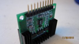
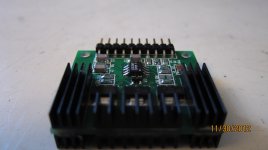
In order to show this isn't a total troll, I'll post my current progress I'd just like to verify the design before posting details, and would greatly enjoy learning how to do this and not rely on my own presuppositions and self-learned processes.
(In case it's not clear from the photo, which it really isn't, this is a dual opamp with one on each "side". Standard SIP-8 pinout, but I also bring out PSU ground and signal ground (which I don't think is necessary, as it's a differential input circuit))
I was wondering if someone could gently outline what sort of tests would be needed to qualify a design that meets the original design goals, in both LTSpice and real-world measurements. Ideally, even a set of LTSpice files with the appropriate tests and maybe even plots, so that we can follow along. For the bench-tests, I think the descriptions can be less verbose.
In order to show this isn't a total troll, I'll post my current progress
I'd just like to verify the design before posting details, and would greatly enjoy learning how to do this and not rely on my own presuppositions and self-learned processes.(In case it's not clear from the photo, which it really isn't, this is a dual opamp with one on each "side". Standard SIP-8 pinout, but I also bring out PSU ground and signal ground (which I don't think is necessary, as it's a differential input circuit))
Attachments
Last edited:
referencing compensation to signal gnd is opportunity for discrete design - can greatly improve PSRR
Cdom PSRR compensation is shown by Self, "Negative Supply-Rail Rejection" p290+ in the 5th ed of his amplifier book (and he's up to 11 in his numberd distortions)
and one of my favorite references:
“A General Relationship Between Amplifier Parameters, And Its Application to PSRR Improvement” E Sackinger, J Groette, W Guggenbuhl, IEEE Trans CAS vol 38, #10 10/83 pp 1171-1181
CiteSeerX — A General Relationship between Amplifier Parameters and its Application to PSRR Improvement - clik on the cached PDF icon
treats the problem, shows several options to improve PSRR
compensating for 2-pole TMC network can be done by connecting to cascode or duplicating the network and connecting to gnd and mirror or cascode
referencing compensation to signal gnd is opportunity for discrete design - can greatly improve PSRR
One of my main reasons for persuing this topology. The AD797 would work fine this way but having a ground pin on an IC op-amp "is just not done". I assure folks the bypassing is much more critical with compensation to the rails.
- Home
- Source & Line
- Analog Line Level
- Discrete Opamp Open Design