what source do you have?
and you connect the lock to the dac?
thanks
and you connect the lock to the dac?
thanks
Hi Anton, happy holidays.
I soldered mine with a 30watt iron with quite a large pointy tip, but I managed.
I socket-ed the IC because I didn't want to risk frying it, does it matter much?
I've had a short listen since and initially I've found that the player may be better as a player than a transport now, given that my Dac is chinese modded as per
http://www.diyaudio.com/forums/digital-source/186245-dac-2496-ak4393-dac-kit-cs8416-ak4393-5532-a.html
This needs more investigation so I'll be doing more comparisons with and without the DAC.
Probably not, my records show that Andrea didn't buy an AC kitset. Assuming that battery was a good DC supply (which it probably was), the AC kitset performance would probably be the same or very slightly worse. The differential oscillator and comparator rejects PSU noise well, and the two level regulation should cut out most PSU noise anyway.
All the components for the kitsets have now arrived.
All the components for the kitsets have now arrived.
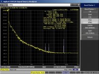
when jitter was tested clock was powered with battery
can we see jitter level of AC pcb
This is the phase noise plot and jitter of the same oscillator AC powered.
Keep in mind that I use an LC filter after battery (10mH/15000 uF) because typically battery is noisier than AC regulated supply.
Andrea
Attachments
Made a Radio Shack run...got er together and here is where I'm using it...
An externally hosted image should be here but it was not working when we last tested it.
An externally hosted image should be here but it was not working when we last tested it.
An externally hosted image should be here but it was not working when we last tested it.
Sorry about this missing resistors, I can send some out to you if you'd like. The connector is an SMB type, there are plenty of cables with this connector on eBay. You can get something like this one, cut one end off, strip and break out the core and shield and solder it to the PCB pads.
Remember to keep the clock output cable as short as possible, I would flip the PCB 180°. It's much better to have a longer DC cable. It's also a good idea to twist the DC wires together.
Remember to keep the clock output cable as short as possible, I would flip the PCB 180°. It's much better to have a longer DC cable. It's also a good idea to twist the DC wires together.
")

Sorry about this missing resistors, I can send some out to you if you'd like. The connector is an SMB type, there are plenty of cables with this connector on eBay. You can get something like this one, cut one end off, strip and break out the core and shield and solder it to the PCB pads.
Remember to keep the clock output cable as short as possible, I would flip the PCB 180°. It's much better to have a longer DC cable. It's also a good idea to twist the DC wires together.
50 Ohm type is what I want for this application?
- Status
- This old topic is closed. If you want to reopen this topic, contact a moderator using the "Report Post" button.
- Home
- Group Buys
- Discrete Low Jitter Clock GB