lineup said:The current source sink is maybe 300uA ( 0.5V/1K5 ).
The JFET is biased only like 5-10uA !!!! ( 0.6V / 100K )
leaving the rest, 290uA for the PNP bipolar.
I Would expect to bias JFET at least 50-100uA
and leave 200-250uA for PNP.
In my understanding this should improve performance quite a bit.
[/B][/QUOTE]
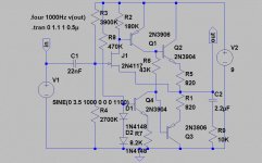
According to the sim, the current sink only sinks 200uA (I made the resistor on its base reasonably high.
Of that, the JFET gets 7uA and the rest goes to the PNP. On reflection it's running rather lean. By dropping R1 from 100K to 22K, this puts a rather more healthy 25uA through the JFET.
Interestingly enough, at 7uA it still simulates quite well. (THD=0.018% with 1V RMS 1KHz input).
Cheers,
Suzy
G.Kleinschmidt said:
Errmmmm.......virtually any nonlinear active device employed in a low level amplifer has potential to rectify and detect and/or amplify stray AM RF signals - and that includes jfets.
BTW, I also restore WWII RF transmitters and design and build RF HF (AM, SSB, CW, FSK, etc) transmitters and associated audio processing gear. I do have a little experience with the problems of low level audio signal amplification (eg from microphones) in the presence of high level RF fields.
Cheers,
Glen
Excellent! Now, assume that "rf" is high end of spectrum of gutar signal...
")
G.Kleinschmidt said:
but a 1.5k resistor in that circuit will sink more than 2mA. The whole point here was to design a low current (~200uA) design to run off batteries for a long time.
Really?

I thoght, the main point was to transfer beautiful music from guitar pickup through a cable that has some capacitance... Sorry, if I misunderstood you guys... Go ahead and save batteries!

PS: I don't speak of coupling capacitor that in combination with emitter follower generates "farting distortions", it is a term invented by guitarists.

suzyj said:
It's a pity you can't see the schematic. I can email you a copy if you like. The modification replaces the 15K resistor in the original circuit with a constant current source, using an MMBTA06 npn transistor. The base is biased to ~1.2V with a pair of 1n4148 diodes to ground, and a 330K resistor to +9V, and there's a 1K5 resistor from the emitter to ground. This results in ~200uA quiescent current (at 9V).
Cheers,
Suzy
Hey, I can see it now (I don't know what is going on).
I reckon the circuit you've got there should suit the intended purpose. After all, 200uA can charge 100pF to 200V in 100uS!
Vc = (Ic/C)t
It probably would be a bit of an overkill to better that.
Cheers,
Glen
suzyj said:
According to the sim, the current sink only sinks 200uA (I made the resistor on its base reasonably high.
Of that, the JFET gets 7uA and the rest goes to the PNP. On reflection it's running rather lean. By dropping R1 from 100K to 22K, this puts a rather more healthy 25uA through the JFET.
Interestingly enough, at 7uA it still simulates quite well. (THD=0.018% with 1V RMS 1KHz input).
Cheers,
Suzy
THD=0.018% with 1V RMS 1KHz input
-------------------------------------------------------------
I guess the load is 10kohm. Gives +-140uA.
25uA in JFET may be close to the optimal value, for only 200uA CCS.
25uA + 175uA idle.
Gives +-140uA making the PNP bipolar operate:
35uA - 315uA, at 1 V RMS output into 10k.
As the main quality here is determined by the JFET linearity of operation,
it would be interesting to see
the same THD for 22k(25-30uA) in PNP Base-Emitter, instead of 100k(6-7uA)
If you dare to post it
at the risk my suggestion was an improvement .....I agree, THD=0.018% is good. Maybe better than we ever need here!
But when we are talking only +-1.414 Volt 1 kHz into 10 kohm
it does not take any advanced discrete buffer circuit
to get close to THD=0.001%
or even below my Distortion Analyzer measurable level, -100dB.
At least not in my Simulator ( MultiSim) using my circuits.
Cheers & Regards
lineup
Originally posted by Wavebourn

Excellent! Now, assume that "rf" is high end of spectrum of gutar signal...
Really?
I thoght, the main point was to transfer beautiful music from guitar pickup through a cable that has some capacitance... Sorry, if I misunderstood you guys... Go ahead and save batteries!
PS: I don't speak of coupling capacitor that in combination with emitter follower generates "farting distortions", it is a term invented by guitarists.
lineup said:
As the main quality here is determined by the JFET linearity of operation,
it would be interesting to see
the same THD for 22k(25-30uA) in PNP Base-Emitter, instead of 100k(6-7uA)
If you dare to post it
0.020% with 22K (1KHz, 1V RMS, 10K load)
G.Kleinschmidt said:
Don't worry. He's a valve guy. There's no use trying to reason with them.
Cheers,
Suzy
lineup said:
But when we are talking only +-1.414 Volt 1 kHz into 10 kohm
it does not take any advanced discrete buffer circuit
to get close to THD=0.001%
or even below my Distortion Analyzer measurable level, -100dB.
At least not in my Simulator ( MultiSim) using my circuits.
I've done 0.0013% (1KHz 28V RMS into 8 ohm), but that was burning rather more power than 200uA x 9V, and a fairly complex circuit (http://www.littlefishbicycles.com/poweramp/index.html). Incidentally, that's my distortion analyser's noise floor.
Getting good performance with really low power is good fun.
Cheers,
Suzy
Ironic.......
Nice, Suzy...... that's pretty much how I feel about the staunch objectivists. You should not dismiss them.
Cheers,
Hugh
From SuzyJ: Don't worry. He's a valve guy. There's no use trying to reason with them.
Nice, Suzy...... that's pretty much how I feel about the staunch objectivists. You should not dismiss them.
Cheers,
Hugh
( Are you really a woman??suzyj said:
http://www.littlefishbicycles.com/poweramp/index.html
Incidentally, that's my distortion analyser's noise floor.
Getting good performance with really low power is good fun.
.
Yes, I think I did see some picture of you, with your interesting bikes)
Yes, I agree fully, suzyj.
I find it is most great fun and a challenge
to squeeze out good performance,
when you are playing with restrictions of:
- simple & small mini discrete circuit
- very low power drawn = 9V battery
*Note: 9 Volt cells packages (6x1.5V)
has less than 50% total capacity, (mAh - milliampere-hours)
compared to if using 6 pcs AA, LR6 batteries.
###########################################
As I mentioned before
making a simple regulator for battery operation,
using as low self consumption as 100uA
while keeping very high prestanda,
(Low voltage drop-out; ~0.15V-0.20V; output voltage precision, with both good line and load regulation.)
- is just that: Great fun!
.. if you end up coming close to your specifications.
By the way, I think it is not impossible
to reach down to 50uA supply current for my 7.200 Volt precision regulator.
At the cost of a little bit of performance.
--------------------------------------
Your specifications are in post #1 here.
They are really not too easy to reach to 100%.
Not while using only 200ua ...
Use of JFET helps a bit, they take almost no bias current.
The other fun and great with low power Battery circuits + small transistors
is that it cost almost nothing to TEST THEM in REALITY Build!
Done quickly at your lab veroboards or similiar.
Regards
lineup
lineup said:( Are you really a woman??
Yes, I think I did see some picture of you, with your interesting bikes)
<grin> I was last time I checked. I actually get asked that more often than you might think - must be an engineering thing.
Incidentally, the photo on my web site is a shocker - it was taken at the end of a 400km ride, and I wasn't exactly looking my best. There are a couple of better photos on my work's website
lineup said:*Note: 9 Volt cells packages (6x1.5V)
has less than 50% total capacity, (mAh - milliampere-hours)
compared to if using 6 pcs AA, LR6 batteries.
I'm toying with using a little step-up converter on a 3V lithium cell.
A 9V battery gives me 500mAh. A 3V lithium CR123 cell gives me 1500mAh at 3V. If I step it up to 9V using an efficient converter, I can get close to the same capacity as a 9V battery, in a package ~1/2 the volume (good for hiding in my guitar, in which a 9V battery won't fit without some surgery).
Alternatively, I could use a pair of 3V lithium cells, and get double the battery life...
lineup said:The other fun and great with low power Battery circuits + small transistors
is that it cost almost nothing to TEST THEM in REALITY Build!
Done quickly at your lab veroboards or similiar.
This is a huge advantage. My day job is IC design. A run of prototype chips costs ~$40K US. It's horrendously stressful sending off the design files, as there's no way to fix mistakes without doing another iteration.
It's much more enjoyable doing designs where if I screw up, I can just cut tracks etc.
Cheers,
Suzy
SAFT www.saftbatteries.com litium lithium battery
I have done some research for Litium cells.
more precise called 'Thionyl' or something like this.
Lithium, can have 3.0-3.6 Volt nominal.
Some variants of them have a superior extremely flat voltage
until they are empty.
Why this research?
Because of their no-slope-during-4-years of constant low currents output
they would make excellent voltage references,
delivering a few uA into Op-Amp or Transistor inputs.
Without any Mains ripple.
--------------------------------------------------------------------------
SAFT.
They have some extremely powerful (BIG) and precise battery.
For use in:
Radio-communication, emergency and security systems,
meters, unmanned vehicles, military applications....
Here is an overview selector pdf
for those different Lithium cells I mean:
http://www.saftbatteries.com/130-Catalogue/PDF/primary_selector_guide.pdf
SAFTBatteries.com - Lithium Page
Homepage:
http://www.saftbatteries.com/
lineup
Lineup Audio Power Research
informations service
Wavebourn said:Ok. Now, what is capacitance of an usual guitar cord? What is the maximum voltage it may be charged on during period of 1/(20 KHz) by your current source with 1.5K in emitter?
Woopsie. I though that you were suggesting replacing the 15k resistor with 1k5. It's easier to work out what's going on now that I can see the circuit. I retract my objection!
suzyj said:Don't worry. He's a valve guy. There's no use trying to reason with them.
LOL!
You know, you're going to start WWIII if you're not carefull.
I'm a bit of a valve guy myself, but not in an audiophile way (perish the thought). I restore lots of old stuff which have valves inside, so I've amassed quite a collection of the glowing bottles (about 5,000-10,000). I like to occasionally incorporate them into my homebrewed projects, but not because I believe they have any magical electrical or sonic properties. I just think they look pretty!
Here’s an AM modulator/exciter design for a HF radio transmitter I just finished:
http://homepages.picknowl.com.au/glenk/ammod.jpg
Twin triodes also make nice JFET substitutes for the input differential amplifier in esoteric audio amplifiers:
http://homepages.picknowl.com.au/glenk/hybrid2.jpg
Cheers,
Glen
Re: SAFT www.saftbatteries.com litium lithium battery
The ones I'm thinking of using are Lithium/Manganese Dioxide. See http://data.energizer.com/PDFs/123.pdf. These cells are quite popular for powering digital cameras, and are thus very easy to get and relatively inexpensive. They are also capable of supplying much more power than Lithium Thionyl Chloride cells, albeit having somewhat lower energy density.
<grin> I've had experience with Wavebourne before. I've put him squarely in the "audiophile tweaker" category, and try my best to just ignore his objections.
A bunch of the guys at work are into valves. My boss insists on hiding boxes full of the damned things in our lab (I suspect his wife won't let them in the house). I was lucky enough to be born well into the solid state age. My only experience with valves has been photomultipliers, and I got a hell of a belt from a PMT early in my career.
I do confess to considering buying a valve amp for my guitar, but I came to my senses and am instead getting a pod DSP amp modeller.
Cheers,
Suzy
lineup said:I have done some research for Litium cells.
more precise called 'Thionyl' or something like this.
The ones I'm thinking of using are Lithium/Manganese Dioxide. See http://data.energizer.com/PDFs/123.pdf. These cells are quite popular for powering digital cameras, and are thus very easy to get and relatively inexpensive. They are also capable of supplying much more power than Lithium Thionyl Chloride cells, albeit having somewhat lower energy density.
G.Kleinschmidt said:
You know, you're going to start WWIII if you're not carefull.
<grin> I've had experience with Wavebourne before. I've put him squarely in the "audiophile tweaker" category, and try my best to just ignore his objections.
G.Kleinschmidt said:I'm a bit of a valve guy myself, but not in an audiophile way
A bunch of the guys at work are into valves. My boss insists on hiding boxes full of the damned things in our lab (I suspect his wife won't let them in the house). I was lucky enough to be born well into the solid state age. My only experience with valves has been photomultipliers, and I got a hell of a belt from a PMT early in my career.
I do confess to considering buying a valve amp for my guitar, but I came to my senses and am instead getting a pod DSP amp modeller.
Cheers,
Suzy
suzyj said:My only experience with valves has been photomultipliers, and I got a hell of a belt from a PMT early in my career.
LOL!
I’ve been zapped several times this week on a PMT supply. My actual job at the moment is with the Government where my main duties involve the design of nuclear and non-nuclear borehole logging tools. My current project, which I’ve been finishing off this week, has been a tool for detecting gamma and neutron radiation. The gamma radiation is detected by a photomultiplier tube coupled to a thallium-activated sodium iodide crystal that emits photons when struck with gamma particles.
The design involved a multi-voltage HV SMPS, preamp circuitry for the PMT, geiger & neutron tubes and a multiple microcontroller based scintillation counter board with serial data telemetry.
With only one spare comm port on my PC, debugging the uC code meant I had to continually swap the RS232 plug between the tool’s serial output and the ISP programmer used for the uC’s. Men are supposed to be crap at multitasking. Well, I’m particularly bad. With my brain occupied with that darn uC code, I just kept forgetting to power down the tool before swapping serial ports. Every time I pushed the fiddly little ISP programmer plug into the header on the PCB my right hand brushed up against the HT board and I got zapped through my fingers.
This happened about 3 or 4 times before I finally zapped myself properly – that is with my right hand on the HT and my left hand firmly griping the grounded chassis. A pair of paralleled 10nF ceramic capacitors charged to 1350V sure packs an unpleasant wallop, right hand through to left hand.
Only then did it occur to me that the HT board could be disconnected, as its operation wasn’t required for the part of the code I was debugging.
D’oh!
And no, I didn’t design any valves into this project – my boss wouldn’t have been impressed.
Cheers,
Glen
Here is a circuit everyone should agree with; it's still the basic Fet/Bjt composite, but with all the bells and whistles added to address most of the objections that have been raised.
Distortion at 100mV rms is now comfortably below 0.001% (<0.01% @1V rms), and the circuit is still capable of delivering more than 7V pp with only 0.25% THD.
Good news for the battery, the quiescent current is below 100µA, yet the push-pull output has the capability to drive any length of cable. Push-pull doesn't necessarily mean class B: normally, the 50µA bias current will be sufficient to keep the circuit in a class A regime. Class B will only be invoked on very short transients, where crossover distortion is unnoticable; not that there is any such distortion: if you substract input from output, you won't be able to see any "structured" residue. The resistance biasing gives a soft transition, and the current sink takes care of the temperature compensation.
A word about the low operating current of J1: it is a common misconception to believe that semiconductors have to be operated above a certain level to give satisfactory operation; this is not the case, at least from a theoretical point of view: Fets are square-law devices, Bjts are exponential devices, and the law extend as low or as high as you care to look; there are practical limitations of course: on the high side, ohmic resistances and focalisation phenomena will come into play, and on the low side, surface currents and noise will set a practical limit, but this limit is surprisingly far: in the golden days of vinyl, it wasn't uncommon to see magnetic cartridge preamplifiers using a big, large area power transistor to minimize noise.
As a foot note: I find this circuit much too complicated for my own taste, and I designed it mainly as an "exercice de style", but it shows that acceptable performances can be obtained without huge overcomplications.
LV
Attachments
OK, here’s my submission. It’s past midnight now and I
really, really should be in bed, but I was stupid enough
to drink a couple of cans of Coca-Cola an hour or so ago.
Approx 300uA quiescent current and check out that
distortion into 10k at 1kHz at 500mV rms! Top that! It
rises to .001% at 1Vrms.
Cheers,
Glen
really, really should be in bed, but I was stupid enough
to drink a couple of cans of Coca-Cola an hour or so ago.
Approx 300uA quiescent current and check out that
distortion into 10k at 1kHz at 500mV rms! Top that! It
rises to .001% at 1Vrms.
Cheers,
Glen
An externally hosted image should be here but it was not working when we last tested it.
G.Kleinschmidt said:Top that! It
rises to .001% at 1Vrms.
Looks like this thread is becoming an on-line contest:
Mine is bigger than yours;
boy's stuff; I'm sure suzy
 will love it.
Elvee said:Looks like this thread is becoming an on-line contest:
Mine is bigger than yours;
boy's stuff; I'm sure suzy
Especially, complementary emitter followers fighting against each other.
Your schematic without them was self-sufficient, more mature, just add a little bit idle current (male muscles in proper place).
Elvee
What kind of JFET is 2N4117.
I have never heard of that one.
Never seen it for sale here in Europe or in my country.
I get it is a N-JFET.
I know no transistor operating very well at 3uA.
Neither JFET or Low-noise small signal like BC550C.
So what kind of strange device is this JFET?
--------------------------------------------------------------------------------
Because it is this input transistor,
that sets the main quality of your amplifier.
Your circuit is great.
But of very little use, to most people in this world
unless they can find and build it with optimal components.
For JFET
I have following options only, to buy and to use:
2SK170, 2SK117 ... both low noise N-JFET.
BF245A, BF245B ... high frequency, low noise N-JFET.
--------------------
It is all good to post circuits with a extremely good performance.
But of limited value and importance to majority of diyaudio members
if components can't easily be found and circuit built.
I always try to use standard, main stream low cost parts for my circuits.
Some live in Africa, South-America and far India / China.
Some are quite poor, I would think, we could say, if compare to a normal western citizen.
Some, still in school, have limited money to spend for audio electronics.
All are not like Mr Pass a rich man from USA living in California, New York or Texas.
I am afraid most are not
Thanks Mr Pass for using easy to get parts
and telling of good easy substitutes for your circuits and amplifiers.
No wonder ordinary people love them and build them in 1000-nds.
-------------------
Elvee,
maybe you can redraw your circuit.
Using some transistor I have heard of.
I have been member here for more than 5 years ( 4.000 posts )
and still can not remember I ever heard of 2N4117.
And nothing wrong with my remembering.
In fact it is VERY GOOD!
Regards
thank you for the best performing circuit, so far
at only 100uA ... this is fantastic
..............................
lineup
Re: Re: SAFT www.saftbatteries.com litium lithium battery
LiMnO2 - litium mangan dioxide
they are the most popular and by this should be lowest in price
these does not have the extreme flat discharge curve
Still curve is not bad, compared to non-litium systems
so, for most applications these will work very well
========================================
LiSO2 - litium sulfur dioxide
these are the ones I was after in my research
they have a straight line of 2.95 volt
while a little current is drawn during constant operation
for at least 3-4 years!!!!!!
My choice for my Reference Voltages, after finishing my research.
Good thing,we have a big supplier in my country
that sells exactly such SAFT Cells ... to a fair price
.. Very fair price!
if I am to believe the performance of these battery
after reading the nice PDF of SAFT with discharge curves
Regards
lineup
suzyj said:
The ones I'm thinking of using are Lithium/Manganese Dioxide.
See http://data.energizer.com/PDFs/123.pdf.
These cells are quite popular for powering digital cameras, and are thus very easy to get and relatively inexpensive.
They are also capable of supplying much more power than Lithium Thionyl Chloride cells,
albeit having somewhat lower energy density.
LiMnO2 - litium mangan dioxide
they are the most popular and by this should be lowest in price
these does not have the extreme flat discharge curve
Still curve is not bad, compared to non-litium systems
so, for most applications these will work very well
========================================
LiSO2 - litium sulfur dioxide
these are the ones I was after in my research
they have a straight line of 2.95 volt
while a little current is drawn during constant operation
for at least 3-4 years!!!!!!
My choice for my Reference Voltages, after finishing my research.
Good thing,we have a big supplier in my country
that sells exactly such SAFT Cells ... to a fair price
.. Very fair price!
if I am to believe the performance of these battery
after reading the nice PDF of SAFT with discharge curves
Regards
lineup
- Status
- This old topic is closed. If you want to reopen this topic, contact a moderator using the "Report Post" button.
- Home
- Live Sound
- Instruments and Amps
- Discrete guitar preamp