Hi!
I experimented a lot with home-made pickups and guitar active circuitary and I play the guitar more then 10 years...
1. OP amp will KILL the guitar! (made only one "good" solution but only worked good with old 741)
2. Low distortion is at the lower end of the list.
3. Low output impedeance DO NOT sound good!
4. Forget the most (hi-fi related) rules when designing guitar preamp.
CHEERS!
Complication is not necessarily synonymous with performance (performance that matters, not simply the spec sheet): look at Micro$oft products for example: they are huge, overblown, take lots of resources yet compare unfavourably with lean and mean freeware.
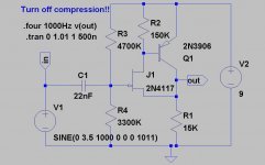
Here is an example of a basic composite buffer. The distortion is acceptable, but a shade higher than the 0.001% boasted by suzy.
More importantly, it is able to handle signals of more than 7V pp, an important consideration if you want to be sure the first cycle after a string is plucked is not clipped, specially when the battery reaches its end of life voltage.
If you find this circuit too basic, you can always improve it by adding an output buffer, a current sink biasing, etc etc.
Attachments
Nice circuit Elvee.
I don't think anyone's asked - what kind of music will Suzy be playing?
I think low - z pickups with preamp have been tried before, iirc jazz players like them, but for most other styles of music I doubt they're suitable. Then again, I think Suzy's approaching this as an engineer, (a valid approach), not a musician?
Pete McK
Then again, I think Suzy's approaching this as an engineer, (a valid approach), not a musician?
That`s the problem ! This approach IS valid, but not much of help in this case.

EXPERIMENT!
PeteMcK said:Nice circuit Elvee.
I don't think anyone's asked - what kind of music will Suzy be playing?
I think low - z pickups with preamp have been tried before, iirc jazz players like them, but for most other styles of music I doubt they're suitable. Then again, I think Suzy's approaching this as an engineer, (a valid approach), not a musician?
Pete McK
I agree. Elvee's circuit is really remarkable. I must confess a tendency towards overcomplexity.
As for music, I'm only a beginner, but so far I've been playing mainly blues and rock, with a little folk (that I really should use an acoustic guitar for) thrown in.
Regardless of music style though, I can't see that having a ~1MOhm output impedance on your guitar can help anyone. Just changing the lead will change the response.
Cheers,
Suzy
suzyj said:
I agree. Elvee's circuit is really remarkable. I must confess a tendency towards overcomplexity.
Problem is it can only actively source current into the lead capacitance. On negative swings you're relying on the 15k source-ground resistor to discharge it. You can reduce the value of this resistor to improve the performance, but that will increase the quiescent current.
A complementary push-pull output stage with low quiescent current could actively source and sink current into the lead/load capacitance, but with appreciably more distortion. Poke the push-pull output stage into a discrete op-amp though, enclosed within the negative feedback loop, and you’re distortion woe’s are solved!
Cheers,
Glen
G.Kleinschmidt said:
Poke the push-pull output stage into a discrete op-amp though, enclosed within the negative feedback loop, and you’re distortion woe’s are solved!
Unfortunately very small amount of crossover distortions, nearly unmeasurable, especially when they are symmetrical, kills the life from the sound of guitars and other instruments with audible decay. It was not a joke when I said that remote cuttoff pentode sounds great with guitar despite it's level of harmonical distortions is high and raises up with signal level.
I'd recommend to load a FET follower by a current source that follows input signal. i.e. pull up by a voltage source, pull down by a current source, it is the best that I ever used for sound reproduction. Current source must supply enough of current to drive cord capacitance without audible distortions on high end of the spectrum.
G.Kleinschmidt said:
Problem is it can only actively source current into the lead capacitance.
A current sink in place of the 15K resistor helps. Here's my added complexity:
An externally hosted image should be here but it was not working when we last tested it.
It also lets you get a tad more dynamic range before clipping.
Cheers,
Suzy
Wavebourn said:Unfortunately very small amount of crossover distortions, nearly unmeasurable, especially when they are symmetrical, kills the life from the sound of guitars and other instruments with audible decay. It was not a joke when I said that remote cuttoff pentode sounds great with guitar despite it's level of harmonical distortions is high and raises up with signal level.
I disagree. A well designed, low distortion audio op-amp simply utilised as a line driver will not add an appreciable coloration to the sound of the guitar.
A pentode with high distortion may sound great with a guitar, but that says absolutely nothing for the merits of a low distortion op-amp as a line driver.
Elvee said:
If you find this circuit too basic,
you can always improve it by adding an output buffer,
a current sink biasing, etc etc.
.
In my opinion,
Elvee circuit is about as simple and good
anybody could design this.
In this post in a JFET design topic
I posted 'my ultimate JFET Buffer' topology for low powers:
This is possible also when using single end supply, with very little modification:
http://www.diyaudio.com/forums/showthread.php?postid=1067790#post1067790
=====================================
By the way,
anybody into small signal JFET applications
should NOT MISS this topic:
Current mirrors driving FETs
..... not because me, lineup is telling some good ideas in there
but there are are OTHERS!
")
See My Attachment!
for basic circuit using a very good idea
for a JFET buffer, simple yet good!
Regards
lineup
Attachments

suzyj said:
A current sink in place of the 15K resistor helps. Here's my added complexity:
An externally hosted image should be here but it was not working when we last tested it.
It also lets you get a tad more dynamic range before clipping.
Cheers,
Suzy
I can't see it! My current server blocks your website
A current sink will improve it, but it still won't be as good at driving line capacitance as a push-pull stage for a given value of quiescent current.
Cheers,
Glen
suzyj said:
A current sink in place of the 15K resistor helps. Here's my added complexity:
An externally hosted image should be here but it was not working when we last tested it.
It also lets you get a tad more dynamic range before clipping.
Cheers,
Suzy
Ok. Now, what is capacitance of an usual guitar cord? What is the maximum voltage it may be charged on during period of 1/(20 KHz) by your current source with 1.5K in emitter?
G.Kleinschmidt said:
I disagree. A well designed, low distortion audio op-amp simply utilised as a line driver will not add an appreciable coloration to the sound of the guitar.
Is this mantra from web sites of opamp manufacturers? So called well designed audio amps are amps that are less usable for more precision purposes, roughly speaking "left-overs".
G.Kleinschmidt said:
A current sink will improve it, but it still won't be as good at driving line capacitance as a push-pull stage for a given value of quiescent current.
Again, "blessed who believeth" (C)

What happens between bases and emitters of your push-pull stage when rectified signal will be applied to them?
(cathode follower loaded by capacitance was used successfully long time ago for AM demodulation).
Wavebourn said:
Again, "blessed who believeth" (C)
What happens between bases and emitters of your push-pull stage when rectified signal will be applied to them?
(cathode follower loaded by capacitance was used successfully long time ago for AM demodulation).
Errmmmm.......virtually any nonlinear active device employed in a low level amplifer has potential to rectify and detect and/or amplify stray AM RF signals - and that includes jfets.
BTW, I also restore WWII RF transmitters and design and build RF HF (AM, SSB, CW, FSK, etc) transmitters and associated audio processing gear. I do have a little experience with the problems of low level audio signal amplification (eg from microphones) in the presence of high level RF fields.
Cheers,
Glen
Wavebourn said:
Ok. Now, what is capacitance of an usual guitar cord? What is the maximum voltage it may be charged on during period of 1/(20 KHz) by your current source with 1.5K in emitter?
but a 1.5k resistor in that circuit will sink more than 2mA. The whole point here was to design a low current (~200uA) design to run off batteries for a long time.
Is this mantra from web sites of opamp manufacturers? So called well designed audio amps are amps that are less usable for more precision purposes, roughly speaking "left-overs".
Huh? We were talking about designing a DISCRETE op-amp, not using a commercial unit.
G.Kleinschmidt said:but a 1.5k resistor in that circuit will sink more than 2mA. The whole point here was to design a low current (~200uA) design to run off batteries for a long time.
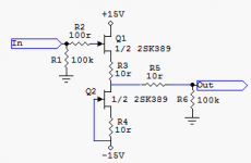
It's a pity you can't see the schematic. I can email you a copy if you like. The modification replaces the 15K resistor in the original circuit with a constant current source, using an MMBTA06 npn transistor. The base is biased to ~1.2V with a pair of 1n4148 diodes to ground, and a 330K resistor to +9V, and there's a 1K5 resistor from the emitter to ground. This results in ~200uA quiescent current (at 9V).
Cheers,
Suzy
ok, as a low level op-amp user I can't comment on the circuits , but I can say:
Llithium batteries aren't that expensive if you search a bit!
I mainly use one or two CR2032 as either 3V or 6V /+-3V for my tiny mic preamps.
They cost 0,45 Euro-Cents and got 200mAh. That's quite a lot for the size...
But if you got the space, me too I'd use something bigger. (in ALkaline or NiMH)
Cheers,
Dominique
, but I can say:Llithium batteries aren't that expensive if you search a bit!
I mainly use one or two CR2032 as either 3V or 6V /+-3V for my tiny mic preamps.
They cost 0,45 Euro-Cents and got 200mAh. That's quite a lot for the size...
But if you got the space, me too I'd use something bigger. (in ALkaline or NiMH)
Cheers,
Dominique
An externally hosted image should be here but it was not working when we last tested it.
guitar_pre_2.gif
I the latest suzyj circuit, guitar_pre_2.gif
I can not quite understand ....
The current source sink is maybe 300uA ( 0.5V/1K5 ).
The JFET is biased only like 5-10uA !!!! ( 0.6V / 100K )
leaving the rest, 290uA for the PNP bipolar.
I Would expect to bias JFET at least 50-100uA
and leave 200-250uA for PNP.
In my understanding this should improve performance quite a bit.
Any transistor, JFET or BJT running almost no current and COLD
operates in the turn-on, non-linear region of transistor curve.
Does not matter if is MOS, FET, BJT or whatever.
This part of the curve, not being very linear!
is also one of the reasons for Zero Crossing distortion.
It is like a car engine, when cold or working at very low, idle RPM
it wont perform well.
It will need a certain RPM to get into best working region.
In the other end, if too many RPM ( rotations per minute )
the car engine will get worse performance again.
This is the reason most cars needs a GEAR Box.
1-2-3-4-5overdrive, and Backwards GEAR.
Ask the Formula One teams, they would know about this
If they do not know this, they are probably a couple of minutes behind Michael Schumacher,
each and every lap ....
lineup
- not into formula one cars - but into formula one diy amplifiers -
- Status
- This old topic is closed. If you want to reopen this topic, contact a moderator using the "Report Post" button.
- Home
- Live Sound
- Instruments and Amps
- Discrete guitar preamp