Agreed - they must be delt with (and I prefere diffusion).We are typing past each other, but yes, you don't want those reflections. They need to be dealt with somehow.
But with a null angled at ceiling, the mirrored speaker will have a tonality with a cancellation at the cross over freq.
Markus
Considering second oder effects, yes their will be an effect on the power response due to the vertical lobes and this is likely to be audible. To what extent depends on a lot of factors, mostly having to do with the room. If the floor and ceiling are fairly well absorbing, but the side walls are all highly reflective (as I suggest and do in my designs) then this issue is minimized - I would say to the point of being insignificant. Other rooms will differ in this regard.
I believe that power response is like RT, it's not wrong but but it simply doesn't tell us what we would need to know and that is the reflection pattern. Now what is the ideal reflection pattern? I don't know.
But with a null angled at ceiling, the mirrored speaker will have a tonality with a cancellation at the cross over freq.
Not if there is no reflection. Thats the point.
But with a null angled at ceiling, the mirrored speaker will have a tonality with a cancellation at the cross over freq.
With no null angled at the ceiling it will have nulls elsewhere determined by the path-lengths via the ceiling. So what ? Keep in mind that not everyone wants diffusors on the ceiling at home but most people wouldn't mind some carpet on the floor.
According to this famous gentleman the most important parameter is power response.
AES Oral History Project Gallery Edgar Villchur - Loudspeaker Performance
Many nulls in crossovers are usually accompanied by an increase in radiated power at another angle and therefore the total power response might still be quite linear.
Regards
Charles
According to this famous gentleman the most important parameter is power response.
AES Oral History Project Gallery Edgar Villchur - Loudspeaker Performance
He says that power response becomes the most important element of speaker performance in "reverberant rooms", implying we all listen in such rooms - do we? I think defining "when, what, arrives where" is more helpful because it accounts for all effects the speaker and/or the room might have.
Many nulls in crossovers are usually accompanied by an increase in radiated power at another angle and therefore the total power response might still be quite linear.
Regards
Charles
That isn't true of the interference at the crossover point. There is always a significant effect on the radiated power.
I have to admit that this statement of mine was too general.
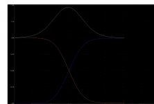
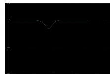
Below you can see the result of the polrar-response simulation of a symmetrical transient-perfect constant-voltage crossover. The drivers were assumed to be point sources with a center to center distance of 30 cm (widerange plus woofer). The crossover frequency is 300 Hz. I think that the curves would be a little "flatter" with the real-world drivers compared to the sim with point-sources.
Curves are displayed for the vertical angles of +- 15 degress, +-30 degrees and +- 45 degrees. As one can see the lack of pressure for upward angles could be reasonably made up for by the increase in pressure at the downward angles. I will search for the sim and try what happens when I sum them geometrically.
I am aware of course that there will be some interaction of undefined nature with the room acoustics. The practice will show how well it actually works.
Regards
Charles
Attachments
According to this famous gentleman the most important parameter is power response.
AES Oral History Project Gallery Edgar Villchur - Loudspeaker Performance
Charles
And that was commonly believed in the 50s and 60s.
More recent studies show the ear's ability to focus through the reverberent field on the direct sound, at least for upper frequencies. This was discussed extensively in the previous thread.
Your off axis curve family is interesting. If you take enough different angles you will notice that an "error envelope" forms, the outer boundary of the various response angles. You can also draw it directly by zeroing out the phase of both drivers. Then add the two bandpasses together for the upper boundary and subtract the two for the lower boundary.
Regards,
David S.
I have to admit that this statement of mine was too general.
I am aware of course that there will be some interaction of undefined nature with the room acoustics. The practice will show how well it actually works.
Regards
Charles
It may be true of some crossovers, but it won't be true in general - I think that you are agreeing with that.
Dave wrote:
Thats the part that I understand - but I somehow don't get :
Earl wrote:
The answer is a very short one: "Yes, definitely!"
Regards
Charles
Your off axis curve family is interesting. If you take enough different angles you will notice that an "error envelope" forms, the outer boundary of the various response angles.
Thats the part that I understand - but I somehow don't get :
You can also draw it directly by zeroing out the phase of both drivers. Then add the two bandpasses together for the upper boundary and subtract the two for the lower boundary.
Earl wrote:
It may be true of some crossovers, but it won't be true in general - I think that you are agreeing with that.
The answer is a very short one: "Yes, definitely!"
Regards
Charles
Sorry if I was being unclear.
I've seen a number of system simulations with time delay between sections as a variable. You always see, if you plot enough samples, that for any particular delay time between between sections there is an upper boundary that no curve exceeds and a lower boundary that none goes below. A particular curve (simulated angle) hits the upper boundary for any frequency where both curves happen to have exactly the same phase. At other frequencies it will hit the lower boundary for any frequency where they both happen to be out of phase.
With some software you can manipulate the phase. If you opened the file for the lower section, say, and replaced all the phase data with zero degrees, then did the same for the upper section, you could add them together and get the absolute upper boundary that none of the particular delay (angle) simulations would exceed.
Conversely, if you set the low pass phase to a constant zero degrees and the high pass to a constant 180 degrees, then those 2 sections added would trace out the lower boundary.
Right?
David S.
Ahhh - now I see. Thanks.
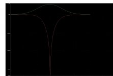
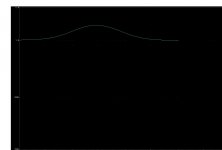
It sounds logical after some tinkering but the lower-boundary might be a little strange to interpret with the negative-going values that are generated, although they just show the absolute level simply out of phase.
Below is the sim for the aforementioned crossover. I did a second one with the negative boundary shown as absolute, such that it can be displayed in logarithmic form.
Regards
Charles
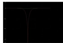
Attachments
Thats it. Good plots.
I'm not saying that it is super significant but it does reveal the range of responses that the off axis curves will be bounded by.
Now, if we set one of the curves to 90 (instead of 0 or 180) is that the power response of the combination? (i think it depends on driver spacing.)
David
I'm not saying that it is super significant but it does reveal the range of responses that the off axis curves will be bounded by.
Now, if we set one of the curves to 90 (instead of 0 or 180) is that the power response of the combination? (i think it depends on driver spacing.)
David
. I did a second one with the negative boundary shown as absolute, such that it can be displayed in logarithmic form.
Regards
Charles
Yes, it makes more sense as a log ( dB) plot.
David
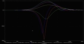
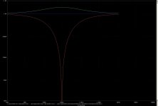
I also did a sim of the boundaries and the power response for the classic 1st order crossover. I put all the traces on the same sheet. If someone is interested I can also post the curves for 15, 30 and 45 degrees.
The advantage of this one is clearly the power response which is linear (which would also be linear for all the odd-order Buttwerworth crossovers). Less nice is the fact that the frequency range - where the upper and lower boundaries are higher or lower than one - is much wider than for the second order TP and the LR4 crossover. OTOH the maximum height of the envelope is lower than the 2nd order tP one's.
Regards
Charles
Attachments
Note that your Pythagorous sum of the highpass/lowpass is the same as my suggested 90 degree sum. You calculate it directly. Setting the curves to 90 degrees apart would have the complex vector addition of the program summing it.
Drivers closer than 1/2 wavelength apart will possibly sum higher.
Interesting results but I wouldn't advocate people design based on a networks predicted power response. You will see in these plots the advantage of higher order networks in reducing the potential error envelope. Some people have had sucess with very high order DSP filters, although there are studies suggesting you can go too far.
David S.
Hi David
I did these things because I wanted to compare different transient perfect (or improved) crossover topologies (the LR was just done to see how these compare with an LR).
It is not a problem to design symmetric and asymmetric constant-voltage transient-perfect crossovers that sum flat on-axis. But I wanted to be sure to choose the one with the least side effects. It will be an asymmetric 2nd-/2nd- order one most probably - just because the unwanted side effects are less extreme compared with the other ones.
Doing a real model in 3D that is simulating the actual driver behaviour more accurately would be very nice but it would mean a lot of work.
I assume that the curves will look a little better with real sources compared to the point-sources used here.
Regards
Charles
Regards
Charles
My experience shows that there should be reverbation in the room, but with certain properties.Not if there is no reflection. Thats the point.
But if we leave the absorption/diffusion discussion, wouldn't it be nicer to treat an "as-linear-as-possible" sound?
- Status
- This old topic is closed. If you want to reopen this topic, contact a moderator using the "Report Post" button.
- Home
- Loudspeakers
- Multi-Way
- Directivity characteristics - what's the effect?