Simulation result shows that when Cosmos impedance is added to my attenuator attenuation is 89.325 times : ) so 1.49Vrms / 89.325 = 16.6mVrms = -35.6dbFS , but my attenuation is probably a bit more so what I got in Multisim around -40db is seems a right value! Thank you so much dkfan9! I think I will stop measurements until frontend get finished, have no sense measuring attenueated small signal while Cosmos is switched to 1.7Vrms, other than that have no sense measuring things without attenuator & while usb isolators is missing for booth Amanero and Cosmos, that way I have ground loops trought my PC.
Last edited:

If the attenuator is needed for now to remove noise from the setup, perhaps try measurements at higher levels which then fit closer to the top of the 1.7V window. This is an interesting project and I'm curious how it ends up performing. I also would be interested in its output impedance and if it changes with volume.
Yes I know, ideal would be using without attenuator and close to 1.7Vrms, but this is an 5V project and without attenuator I have ground loops, I don't have right electronics right now. Frontend is need, its my next plan, another blue alu enclosure mounted at top of ddpd blue enclosure. Frontend I have working in another project, half analog project, and I will port it to ddpd easy. I allready said about sound, also I allready said that I no need measurements at all for ddpd and also that I am ok if I measure even high tnd it won't change my opinion about the sound provided by ddpd, I must say again, nothing I had in my home recently have sound close to sound with full body like trought ddpd. : )
I will try! It will remove ground loop trought Cosmos & Amanero in the same time with my PC. If I get success with measurement setup probably I will try to fine tune dead time inside ddpd, that was the only thing I didn't adjusted fully, right now dead time value is an RCD network which form an propagation delay between high/low around 10ns, I'm believing fine tunning it and ddpd will sound even better, probably not an big diference but enought to make ddpd sound even better.Cosmos ADC has a limited ability to common-mode-out DC - its just a couple of volts... try a cap (or 2)?
//
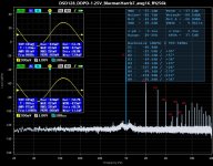
Done using only load resistor 10 ohm, without aux filer, without attenuator, without ac coupling capacitors, now levels looks almost correct.
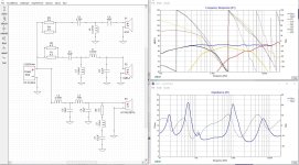
Output impedance:
DDPD=1.25V --- 450mVrms when no load --- 309mVrms while 10 ohm load --- = 4.56 ohm output impedance
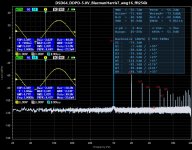
DDPD=5V --- 1.77Vrms whwn no load --- 1.53Vrms while 10 ohm load --- = 1.57 ohm output impedance
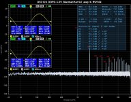
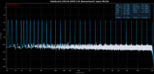
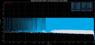
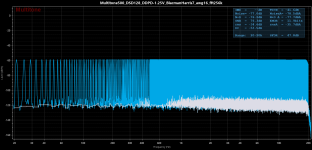
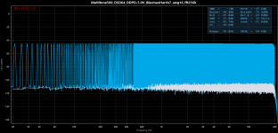
I'm tried dsd256 and results is not good, maybe because of fixed dead time which is now around 10ns. This DDPD right now is capable only to dsd64 and dsd128! I will play with dead time adjustement, maybe I get some better measurement results, in the same time maybe even dsd256 and up get working! Deadtime maybe is not need at all? I will focus on DSD64 and try to find right and optimal dead time, next day!
First 4 pictures contain booth Multitone result and also my hardware osciloscope measured at load resistor. My measurements:
Output impedance:
DDPD=1.25V --- 450mVrms when no load --- 309mVrms while 10 ohm load --- = 4.56 ohm output impedance
DDPD=5V --- 1.77Vrms whwn no load --- 1.53Vrms while 10 ohm load --- = 1.57 ohm output impedance
I'm tried dsd256 and results is not good, maybe because of fixed dead time which is now around 10ns. This DDPD right now is capable only to dsd64 and dsd128! I will play with dead time adjustement, maybe I get some better measurement results, in the same time maybe even dsd256 and up get working! Deadtime maybe is not need at all? I will focus on DSD64 and try to find right and optimal dead time, next day!
First 4 pictures contain booth Multitone result and also my hardware osciloscope measured at load resistor. My measurements:
Attachments
-
 DSD64_DDPD-1.25V_BlacmanHarris7_awg16_fft256k.jpg216 KB · Views: 47
 -
 DSD128_DDPD-1.25V_BlacmanHarris7_awg16_fft256k.jpg218.5 KB · Views: 42
 -
 DSD64_DDPD-5.0V_BlacmanHarris7_awg16_fft256k.jpg215.4 KB · Views: 40
 -
 DSD128_DDPD-5.0V_BlacmanHarris7_awg16_fft256k.jpg213.9 KB · Views: 39
 -
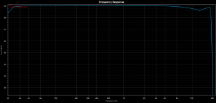 Frequency Response.png13.7 KB · Views: 43
 -
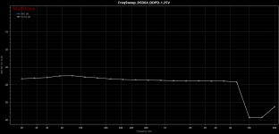 FreqSweep_DSD64_DDPD-1.25V.png15.4 KB · Views: 42
 -
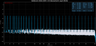 Multitone32_DSD64_DDPD-1.25V_BlacmanHarris7_awg16_fft256k.png42.5 KB · Views: 42
 -
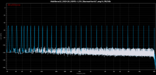 Multitone32_DSD128_DDPD-1.25V_BlacmanHarris7_awg16_fft256k.png36.3 KB · Views: 41
 -
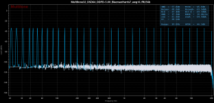 Multitone32_DSD64_DDPD-5.0V_BlacmanHarris7_awg16_fft256k.png37.7 KB · Views: 37
 -
 Multitone32_DSD128_DDPD-5.0V_BlacmanHarris7_awg16_fft256k.png39.8 KB · Views: 37
 -
 Multitone500_DSD64_DDPD-1.25V_BlacmanHarris7_awg16_fft256k.png44.1 KB · Views: 34
 -
 Multitone500_DSD128_DDPD-1.25V_BlacmanHarris7_awg16_fft256k.png43.9 KB · Views: 34
 -
 Multitone500_DSD64_DDPD-5.0V_BlacmanHarris7_awg16_fft256k.png41 KB · Views: 35
 -
 Multitone500_DSD128_DDPD-5.0V_BlacmanHarris7_awg16_fft256k.png41.4 KB · Views: 38
 -
 Multitone500_DSD64_DDPD-1.25V_Spectogram.jpg305.8 KB · Views: 44
Last edited:
I have found also twisted wire pair from-to dut gives diferent result, I have used twisted wire as a better result. Also to note, my Amanero is diy, it didn't play dsd512, might be that my Amanero is not good at all. Also count hacked SMA connectors from ddpd to Amanero, Amanero have clasic pins and my ddpd have coaxial SMA, wire from-to ddpd-Amanero is hacked, on the one side is sma on the other side is pins, its not an optimal interconnection. Final measurements when frontend get done and when all the things get corrected. : )
Last edited:
I don't know how it is calculated. When ddpd is on 1.25V the volume level in my room is allready loud and need to adjust volume by sw, when 5V its very loud, I'm believing 2x 3Wats it have. My speakers is 8 ohm.What output power do you anticipate in 8 ohm?
//
Last edited:
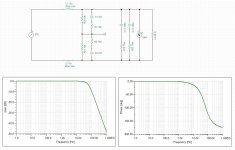
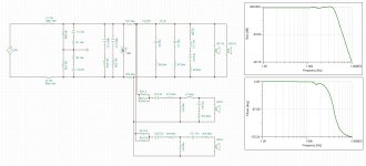
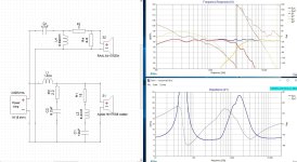
BTL filer used on DDPD, booth simulation with any 8 ohm load and also simulated specialy with my speakers : ) Booth sound amazing, expecialy one which have Raal, attaching boot schematic of my speakers collection, booth is transmission line, designed for my room and listenning position. Ye video from first post is recorded while ddpd sound trought speakers with with Raal, you can hear how it sound booth with an good headphones, recorded not with an good recorder but with an android phone, dynamic can be heard if nothing else. : )
Attachments
Last edited:
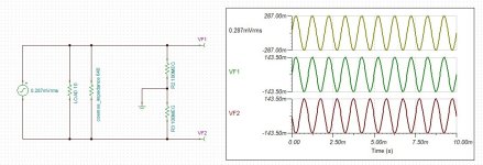
Measurements from post #129 is still wrong! I have no idea whats going on right now, probably Cosmos have some sw setting to be adjusted? Also the impedance at the Cosmos input (640R) has no influence on the measurement result because the current flowing through it is negligible compared to that flowing through the load.Is the 65mV reading with Cosmos connected or without? Just a quick look at the attenuator schematic, 2k output impedance and Cosmos' 640 input impedance is a -12.3dB voltage divider. 64mV is -28.5dB ref 1.7V. Throw in some tolerances and -41.2dB is the right number.
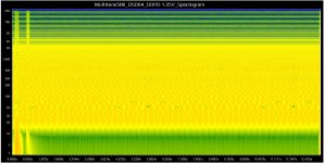
However, the voltage measured by the oscilloscope at the output of the ddpd does not agree with the one seen in the spectra.
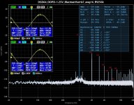
For example, in the first spectrum, the oscilloscope shows 287mVrms, and H1 is at a level of -21.5dB ref. 1.7Vrms (Cosmos range), or 143mVrms, which is exactly half of 287mVrms. I'm checked xlr cable and also by multimetre gnd position inside cosmos xlr, all is right here. What might be isue? Looks like cosmos see this as a single ended. Does cosmos maybe have something in their sw configuration in relation to SE/DIFF ?
Attachments
Last edited:
Please take a look at this picture, notice osciloscope Vrms measured diferentialy at the load resistor, I have measured it 287mVrms. Now look into H1 , notice -21.5db, thats half of my osciloscope measurement! So all measurement I done is invalid because something is wrong here. Looks like cosmos see my diff outpur as a single ended. Also spectral analise shows some iregualities at first 1 seccond. Something is wrong in my measurement setup and I have no idea right now what. Somebody say that Cosmos starts in the so-called Mono mode, which means that the signal must be fed simultaneously to both of its inputs, which achieves a 3dB noise reduction. If the right input is empty (as like in my case), then the result is half the voltage of the left input and this is most likely the cause of the error. I realy have no idea how to connect Cosmos with my ddpd.
Attachments
Last edited:
Cosmos isnt an absolute voltage measuring device. If you want to use it as that you need to calibrate it to 0dBfs. You figure "21,5db" is just a relative number - it doesn't mean anything in the real world.
To get Cosmos to be an ordinary Stereo ADC, you have to set the "Volume" (I know, strange, but thats how you do it) in the program that you connect to Cosmos with to zero. You will see the LEDs on the front blink green when you have entered stereo mode.
This si a bit of a guess... isnt it that in mono mode the Left input is connected to both channel HW and thus get a better SNR - its not that you have to have the same input on both XLR connectors...
//
Its always orange!
I still not understand their text -> https://e1dashz.wixsite.com/index/cosmos-adc
what this mean? I'm using only left XLR input of the Cosmos, is it wrong? I lost two days in this and I still not understand what I have doing wrong. Even I am unable to open .doc file, don't using those software for years, only pdf files.
I still not understand their text -> https://e1dashz.wixsite.com/index/cosmos-adc
MONO/STEREO modes are switchable by the UAC2 volume commands, for example, if your Windows volume slider position is less than 50%(0 to 49%) the device works as 2 channel ADC, if more than 50% it is a MONO ADC with summed Left+Right inputs mapped on the Left channel(Right input is always mapped to the Right channel). In the MONO mode, both channels need to be tied together L+ to R+, L- to R-.
what this mean? I'm using only left XLR input of the Cosmos, is it wrong? I lost two days in this and I still not understand what I have doing wrong. Even I am unable to open .doc file, don't using those software for years, only pdf files.
Last edited:
I don't like that web page so I will not follow it. But when I hook the ADC up to my Mac and use the Volume slider in my "Sound" settings, setting the Volume to 0 - the leds on the front for each channel will flash green.
So you need to get to apoint where you can control the Input aspects of the connected USB sound device (the Cosmos in this case) - the draw a slider to set Volume to 0 and it will flash green. Below is not the specific case but just showing what I tried and it worked.

OK, so it looks like the + input need to be fed to both XLR + pins if you want to run it in Mono.
Looking at the performance of your DAC I dont think at this stage you need to optimise on the last dBs but rather on getting your measuremnts up in an orderly fashion. This means just one channel, using it in Stereo mode.
//
So you need to get to apoint where you can control the Input aspects of the connected USB sound device (the Cosmos in this case) - the draw a slider to set Volume to 0 and it will flash green. Below is not the specific case but just showing what I tried and it worked.
OK, so it looks like the + input need to be fed to both XLR + pins if you want to run it in Mono.
Looking at the performance of your DAC I dont think at this stage you need to optimise on the last dBs but rather on getting your measuremnts up in an orderly fashion. This means just one channel, using it in Stereo mode.
//
When you have it set to mono mode then you have to use both ADC inputs. However in your digital audio app, the left digital channel will be the sum of the L and R analog input signals. The right digital channel will be only right analog input signal....what this mean?
You're correct, now that you have the filter out of loop, the Cosmos input impedance is irrelevant. Based on the manual snip you posted and @TNT's experiment, setting volume below 50% should fix your 6dB loss. If the Cosmos is currently working in mono mode and you have only one channel hooked up, it's presumably averaging the two channels, one at 287mV RMS and the other at 0 and registering the digital equivalent of 143mV RMS at the ADC output. (I hope that makes sense)Measurements from post #129 is still wrong! I have no idea whats going on right now, probably Cosmos have some sw setting to be adjusted? Also the impedance at the Cosmos input (640R) has no influence on the measurement result because the current flowing through it is negligible compared to that flowing through the load.
However, the voltage measured by the oscilloscope at the output of the ddpd does not agree with the one seen in the spectra.
For example, in the first spectrum, the oscilloscope shows 287mVrms, and H1 is at a level of -21.5dB ref. 1.7Vrms (Cosmos range), or 143mVrms, which is exactly half of 287mVrms. I'm checked xlr cable and also by multimetre gnd position inside cosmos xlr, all is right here. What might be isue? Looks like cosmos see this as a single ended. Does cosmos maybe have something in their sw configuration in relation to SE/DIFF ?
- Home
- Amplifiers
- Class D
- Direct Digital Power DAC (DDPD)