Don't have any schematics. (Actually, nothing I've built is in schematic form. Don't believe me? Ask Harry.)
I would use/come up with a diffamp type circuit. Probably current starved to square up the output. ECL, op-amp, whatever. Whatever works. Just as long as it doesn't reflect anything back to the line. The CMRR might not be optimized if I did one, but any CMRR is better than zero, especially if it comes for free as a function of the circuit.
Jocko
Schematics
He draws conceptual schematics once and a while for disscussing a given topology. I don't ever remember seeing part numbers or resistor values on one though. I draw schematics for everything even stuff I never intend on building. It is almost essential when wiring circuits point to point as one can get lost real easily without a map.
H.H.
Improved Interface
Hi All,
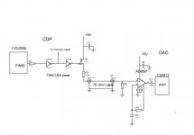
Attached is a improved interface using the AD8561 comparator. It produces a 4.5 V peak to peak signal at the RXP input of the CS8412 digital input receiver. Signal at the input of the comparator is about 1 V p.p.
Sound is much improved , better bass, better texture in the music. It is like tones are started from the fundamental, instead of from a higher overtone. Imaging is also improved. I like it!
Thanks for the hint Jocko! Apparently we need to knock hard on the entrance door of the CS8412.")
Sharp eyed readers will notice the similarity with the KWAK-CLOCK: JFET followed by comparator.
Hi All,
Attached is a improved interface using the AD8561 comparator. It produces a 4.5 V peak to peak signal at the RXP input of the CS8412 digital input receiver. Signal at the input of the comparator is about 1 V p.p.
Sound is much improved , better bass, better texture in the music. It is like tones are started from the fundamental, instead of from a higher overtone. Imaging is also improved. I like it!
Thanks for the hint Jocko! Apparently we need to knock hard on the entrance door of the CS8412.
Sharp eyed readers will notice the similarity with the KWAK-CLOCK: JFET followed by comparator.
Attachments
Digital interface
If your output impedance is 75 ohms and your input impedance is 75 ohms and you are driving at Cmos levels, how do you get 1 volt p-p at comparator. The Crystal likes to be driven at logic levels it also likes even better to be driven differentialy (REAL BIG HINT!) Also I don't think you need the coupling cap into the 8412 since you have a logic level input. I tried the LT1016 comparator and I didn't like it but haven't played with the AD8561. Glad to see you back. I thought we ran you off.
H.H.
Interface
Hi Harry Haller,
No I did not ran off. I had a nasty virus on my computer. I formatted the harddisk and everything looked OK. After that I got a boot disk error and I could not format the harddisk anymore. End of life <B>-KAPUT-</B>
The circuit:
The JFET source follower has a gain less than 1 and the arrangement with the cable gives a 3dB signal loss.
Of course this scheme can be modified to 110 Ohm balanced cable with one or two comparators at the CS8412. This will involve major surgery in my CDP and DAC to install XLR parts. Thanks for the hint; maybe I will try that in the future. I don't think it is a good idea to omit C2 as the input of the 8412 is biased to a other voltage than the comparator ouput. I am using a silvered mica cap for C2.
Standard SPDIF Input Signal
Hi Tiroth,
If you want to use the standard SPDIF input signal with no DC component I would use the same comparator inputstage but with dual +/-5V supplies. That would place the signal nicely in the input common mode range (-5 to +3V) of the AD8561 comparator.
Hi Tiroth,
If you want to use the standard SPDIF input signal with no DC component I would use the same comparator inputstage but with dual +/-5V supplies. That would place the signal nicely in the input common mode range (-5 to +3V) of the AD8561 comparator.
Standard SPDIF Input
Hi Tiroth,
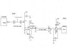
I just gave it a try with dual +/- 5V supplies for the AD8561 comparator (pin#4 connected to -5V).
Much to my own surprise it sounds a lot better that way. Can it be the 5dB better Power Supply Rejection..........?
Also powered the comparator in the KWAK-CLOCK this way: same improvement.
So your question led to a major improvement!
Hi Tiroth,
I just gave it a try with dual +/- 5V supplies for the AD8561 comparator (pin#4 connected to -5V).
Much to my own surprise it sounds a lot better that way. Can it be the 5dB better Power Supply Rejection..........?
Also powered the comparator in the KWAK-CLOCK this way: same improvement.
So your question led to a major improvement!
Pretty interesting! Can I ask why you don't bias the inverting input above ground? Wouldn't this provide better noise rejection?
The designs I have seen that make sense to me use a comparator with its inverting input biased to, say, 50% of the input logic "1". Maybe 100mV for S/PDIF or 2V for AES/EBU.
I think I am getting my comparator tutorial now.
The designs I have seen that make sense to me use a comparator with its inverting input biased to, say, 50% of the input logic "1". Maybe 100mV for S/PDIF or 2V for AES/EBU.
I think I am getting my comparator tutorial now.
SPDIF input receiver
Hi Tiroth,
The trick with the 2k feedback resistor on the comparator is that the negative input is biased to the DC-level of the output.
In this way the trippoint is automatically adjusted to the DC-level of the inputsignal at the positive input.
[One usually sees the negative input connected to the wiper of a pot connected between V+ & V-.] You can also look at the comparator as a unity gain follower at DC.
You asked for a universal circuit and that is what you get. It will work with standarised SPDIF signal (0.5 V p-p; no DC) as well as with my circuit with about 1.3 V p-p AC and considerable DC offset (about 1.5V) on top of this.
The comparator has TTL logic output format. I did understand the CS8412 likes his/her food this way.
- Status
- This old topic is closed. If you want to reopen this topic, contact a moderator using the "Report Post" button.
- Home
- Source & Line
- Digital Source
- Digital transformer