Should the input ground be connected to the center tapped/chassis ground or left separate? It seems the input would have no voltage reference without some connection but it seems that when connected many issues arise.
Yes, it does not needed to be connected to the center tapped, the input signal ground should always be connected to the input stage of the amplifier, you will not hear the sound you need since there is no return path for the input signal.
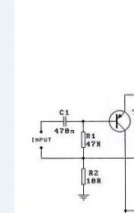
Try adding a 10 ohm 1W resistor on the input to isolate it directly from the power supply ground like the attached image.
I built a current mirror input stage and was testing the output and all failed as soon as I connected this particular ground wire. Another cellphone with no output on the headphone jack, fried soundcard.
Your input and VAS transistor is probably faulty.
Attachments
I also have the idea of substituting a current mirror with 2 NPN and 2 PNP (BC546, BC556) transistors for the input stage.
Do not worry yet yourself with adding current mirror to the circuit, make the circuit you have started working. It just complicate things, thus adding trouble to project circuit.
I keep trying to measure the beta of my BC trasnsistors but the result is always 000. And yes, I am dropping the transistors into the proper slots bon my DMM, C,B,E for BC 546, 556 transistors, NPN, PNP respectively.
If you trust your DMM, your transistors is probably jig.

What impedance was the speaker, and was it clipping?
HD
They were eight ohms and no clipping. They speakers were the AEM two ways which I though were fantastic until I discovered that active speakers make passives sound very ordinary.
Thanks for the reply. I feel there is something else wrong, and it's not the amp but more likely the wiring since there were flames. No AKSA 55 ever behaved like this before. Perhaps you could bring it, you are in Melbourne, I will repair it for you to find out what went wrong.
HD
HD
Thanks, but they were consigned to the electronic recycle a long time ago.Thanks for the reply. I feel there is something else wrong, and it's not the amp but more likely the wiring since there were flames. No AKSA 55 ever behaved like this before. Perhaps you could bring it, you are in Melbourne, I will repair it for you to find out what went wrong.
HD
I am a real novice at this and am using this circuit to learn on. I have been trying to follow the Digi-125 circuit posted by greg but have hit a mental block can’t get it to work and am pulling my hair out.
I simulated the circuit Ok, used Kicad and had some prototype boards made (cannot breadboard to save my life!) but when built I’m just getting a 50hz oscillation at the output. I have checked all pin outs on their respective data sheets and confirmed connections are going where they should. I have built a 2nd board with fresh components but still the same issue. Anyone have any ideas that I may not have tried? Thanks in advance.


I
I simulated the circuit Ok, used Kicad and had some prototype boards made (cannot breadboard to save my life!) but when built I’m just getting a 50hz oscillation at the output. I have checked all pin outs on their respective data sheets and confirmed connections are going where they should. I have built a 2nd board with fresh components but still the same issue. Anyone have any ideas that I may not have tried? Thanks in advance.
I
Please post the Kicad schematic you used (as an image). You did a design rule check I presume? Checked that all the supply voltages are as they should be?I am a real novice at this and am using this circuit to learn on. I have been trying to follow the Digi-125 circuit posted by greg but have hit a mental block can’t get it to work and am pulling my hair out.
I simulated the circuit Ok, used Kicad and had some prototype boards made (cannot breadboard to save my life!) but when built I’m just getting a 50hz oscillation at the output. I have checked all pin outs on their respective data sheets and confirmed connections are going where they should. I have built a 2nd board with fresh components but still the same issue. Anyone have any ideas that I may not have tried? Thanks in advance.

Is there any transistor getting too hot?
Check also the output if there is a DC value.
If you cannot hear anything just by touching the input wire, probably there is something wrong with your LTP. It was previously mentioned that LTP should have a enough gain for it to work, try using different LTP parts.
Check also the output if there is a DC value.
If you cannot hear anything just by touching the input wire, probably there is something wrong with your LTP. It was previously mentioned that LTP should have a enough gain for it to work, try using different LTP parts.


Is that with no input?
A1943 is not conducting, check your connections.
Measure your Vbe if Q4 and Q6 is on.
Emitter of Q4 should be connected to Base of A1943 not to the negative rail.
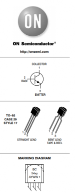
I have attached a snip of the datasheet for BC546 from OnSemi
Try also to replace the front end with higher gain BJT like 2N5401 to start with.
Measure your Vbe if Q4 and Q6 is on.
Emitter of Q4 should be connected to Base of A1943 not to the negative rail.
I have attached a snip of the datasheet for BC546 from OnSemi
Try also to replace the front end with higher gain BJT like 2N5401 to start with.
Attachments

Hi guys, I wrote a whole introduction, being a new member here, if not to hifi and audio - 45+ years experience, though I am not a tech head as such! - and the system wiped it all out and took me back to login again! So, I'm not going to go through system details and why again regarding the DIGI 125, sigh, I'm looking to see if any of the larger circuit boards for the DIGI 125 exist anywhere, since rca radio no longer seems to be around. I have 5 sets of the new original boards, but would love a bigger board if possible, though the small original ones certainly have very short signal paths.
My current DIGI 125 amp is dual mono after the transformer, using 2 x 8000uF Elna caps per channel, POOGE mod type Litz wiring for all power supply cables and solid core elsewhere. Its astonishingly transparent and has wowed audio friends in my main system, fronted by a Technics SL1900 t/t with AT VM95SH cart; CD player with pure silver cables and both running into an Elekit valve pre-amp with the upgrade kit that I assembled with great care myself. Speakers are the knockout top of the line from 1968 Sansui SP300 speakers, with horn mid and top end drivers and 12" bass drivers. At 106dB efficiency, it takes nothing to drive them, although the DIGI 125 still powers them with more oomph than a restored Pioneer SA-5300 10W amp. In saying that, I've run them to bliss with a 2W Peak valve amp.
I'm wanting to build a new DIGI 125 amps based closely on the original circuit, it's been a fabulous result for me for many years, just a little upgrade here and there if possible, such as the BF469/Tosh 2SC5200/2SA1943 combo plus the extra bias diode. I'll continue with the Litz cables and solid core copper, something I've been doing for decades.
- Status
- This old topic is closed. If you want to reopen this topic, contact a moderator using the "Report Post" button.
- Home
- Amplifiers
- Solid State
- DIGI-125 Kit Amplifier Module