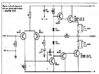
Digi 125
Secondly nobody has suggested any changes or modifications or additions
If Q1 and Q2 are matched for both HFE and VBE, temporarily fit a 10K trimpot in series with the collector of Q2. Adjust so that the difference between the collector voltages of Q1 and Q2 is as close as possible to 0mV. Then replace the trimpot with 1 or 2 MF resistors (series or parallel connected) , chosen to be close to the trimpot resistance used to obtain balance.
Yes, I built several of these many years ago from PCBs purchased from Graham Dicker, and they were just mediocre in their original form.
SandyK
I was thinking about building this (Digi-125) for my first amplifier project, as it has the advantage of being very simple and (hopefully) easy to build, while still producing what many have claimed as decent sound. I plan to fab the PC board myself, so as to beef up the inadaquate solder traces as noted by G.Kleinshmidt. I was considering the following mods, some taken from previous posters on this thread, and wanted to get you all's oppinion on them.
- 2SC5200/2SA1943 for output devices.
- BC556/BC546 for the predrivers. BF459 for the VA transistor.
- 2N5401 for the input stage differential transistors.
- Replace the two 1N914's in the collector of the VA stage with an amplified diode, for more accurate control of the bias. Also mount the amplified diode transistor to the heatsink for better thermal compensation.
- Lower the value of the pole cap in the VA stage to 68pF (possibly replace with a trimmer cap for experamentation)
- Add an output inductor and a zobel network to improve stability.
- Add capacitive coupling at the input.
- Add decoupling caps and/or a low pass filter on both rails to improve power supply rejection.
- Metal film 1% resistors throughout.
Once again i am sort of a noob at this so please be gentle. Thank you to all who have contributed to this tread ... it has been a very intresting read.
Sry but I'd rather suggest some more sophisticated design, especially if it's your first project.
Digi-125 likes oscillating (one reason for that is the OP/driver stage has gain), especially with the fast 2SA/2SC OP devices you mentioned.
Try Rod Elliott's P3A or something similar. Choose a straightforward, stable, and TESTED design. Digi-125 with the modifications you mentioned isn't tested yet. You would be the first prototyper! As first project it's a bad idea.
Gain
Sorry, but I agree with Andy. I think you will run into trouble.
If you really want to try it, don't deviate much from the original design and components.
Also,what we thought sounded decent back then, was very different to what many of would regard as decent these days.
SandyK
Sorry, but I agree with Andy. I think you will run into trouble.
If you really want to try it, don't deviate much from the original design and components.
Also,what we thought sounded decent back then, was very different to what many of would regard as decent these days.
SandyK
hi gain,
If you look at posts #25 and #26 you will see I did similar mods to what you are suggesting. I found the project very satisfying, starting with the basic circuit (with 2SC5200/2SA1943) and changing or adding extra features as suggested by members on the forum.
I found that increasing the bias and adding a bootstrap to the VAS made the most difference, the other changes only made minor improvements.
I changed the VAS trnasistor from a TO92 because it got hot.
So, if you are more interested in learning about amp design and building then do what you suggested, if you want a guaranteed result look for other options.
Soundwise, the final result was surprisingly good, but not in the same league as SandyK amps.
WARNING: I only ever tested with 25 volt rails.
regards
thank you Andy and SnadyK for your input. yes this is most likely taking on too much for a first project. you guys are absolutely right i should not be trying to prototype something new before i at least get a few successful amplifier builds under my belt ... thanks for setting me straight on that. i suppose i was drawn to this circuit because it was the first amp schematic that i could look at and understand the purpose of every single component (im a CS major and not EE but i will be taking some EE courses next year so hopefully will learn much more).
thanks Andy for the suggestion to try the PA3
http://sound.westhost.com/project3a.htm
i will look more into that amp over the weekend or if i do decide to go with the digi125 i will implement the original circuit with no mods.
You mention the digi125 had a tendency to oscillate ... was there ever a solution developed for this? would reducing the gain in the OPS or mabye increasing negative FB help?
Digi-125
So, if you are more interested in learning about amp design and building then do what you suggested, if you want a guaranteed result look for other options.
Good advice Greg !
But try it in the original form first, so you can gauge the extent of the improvements. Also it is best to do one change at a time, then listen. Some changes don't always give the expected results, and this way you will know which change to reverse.
SandyK
hey Greg,
yeah your work on modifying this was one of my primary inspirations for wanting to try the digi125. my goal is to learn, but if i can happen to create a decent sound system in the process then all the better!
i will most likely build the circuit with the original design, get that working (i hope), then try swapping the output devices for the 2SC5200/2SA1943 ... both you and Tomcat said that made a big improvement.
at any rate i will get the original circuit working, then do one mod and get that working, then do another single mod and get that working ... etc.
regards
-John
gain said:
- 2SC5200/2SA1943 for output devices.
- BC556/BC546 for the predrivers. BF459 for the VA transistor.
- 2N5401 for the input stage differential transistors.
- Replace the two 1N914's in the collector of the VA stage with an amplified diode, for more accurate control of the bias. Also mount the amplified diode transistor to the heatsink for better thermal compensation.
- Lower the value of the pole cap in the VA stage to 68pF (possibly replace with a trimmer cap for experamentation)
- Add an output inductor and a zobel network to improve stability.
- Add capacitive coupling at the input.
- Add decoupling caps and/or a low pass filter on both rails to improve power supply rejection.
- Metal film 1% resistors throughout.
The output transistor choice is good.
I don't know how he got away with those little BC transistors for drivers, you could try ZTX653/753 as beefier but still small package. You could also try ZTX653 as the VAS transistor.
Keep the BC transistors for the LTP as they have better noise performance and gain than 2N5401.
Using an amplified diode is a good idea.
Using a trimmer capacitor for stability is probably a bad idea, I dislike trimmers be them capacitors or resistors, unless absolutely necessary as they can go noisy.
By the time you add the other modifications you have changed the amp quite a lot and you might as well throw the Digi-125 name to the distant memory.
The output stage does not have voltage gain, only current gain. The oscillation problems may have been due to lack of Zobel and poor PCB design.
Feel free to add your mods, but as has been pointed out by experienced tweakers already, make sure you do things incrementally so you can observe the differences.
Digi-125
Hugh
Most of the amplifiers they appear in, have supply rails well below
+&-40V. The Digi-125 , as Greg says, is probably not suitable for much more than +&-25V as it stands, unless suitable heatsinking etc. Most constructors wouldn't even have the benefit of the original construction article ? 2SA970 have a VCEo of -120V.
OFF TOPIC.
BTW, re CMs, best results are obtained with well matched devices having a VERY high HFE. Some time back it used to be suggested HFE of 800 (or more) sounded better. In many circuits , MPSA18 are eminently suitable due to their very low cost, and HFEs up to 1,200 or so.
Their voltage ratings don't matter in a typical CM implementation.
Just a thought, while you were around . vhfman (Dave) agrees about this too .
Regards
Alex
AKSA said:Alex,
Could be the low cost and higher Vceo of the 5401 - 150V?
I'm sure there are lower noise devices around with similar Vceo, any ideas? I have seen Japanese devices used here, but can't recall the name.
Cheers,
Hugh
Hi Hugh,
I prefer the Japanese (Toshiba) 2SC2240/2SA970 as small-signal BJTs in audio amplifiers (I mostly use them in the LTP). Check their datasheet, you'll find very nice figures!
They are almost everywhere available and the price is reasonable too.
Thanks Alex,
One point; the very high betas lead to vanishingly low bias currents, and the diode thus has very low Vf, measured around 430mV on a 4148. While this is low, clearly both devices are still operating as transistors, and this is the chief benefit since their transfer functions are much closer.
Andy,
Many thanks, I will delve into it a little further. I now have almost 95Mb in datasheet pdfs!!
Cheers,
Hugh
> I prefer the Japanese (Toshiba) 2SC2240/2SA970 as small-signal BJTs in audio amplifiers
I can second that. Also 2SC1815 and complementary, if you can live with the somewhat lower voltage. VERY linear hfe with Ic over a wide range.
> I now have almost 95Mb in datasheet pdfs!!
That is still less than 10% of the smallest USB stick still available !!
You can hardly get anything 512MB or less nowadays .....
")
Patrick
I can second that. Also 2SC1815 and complementary, if you can live with the somewhat lower voltage. VERY linear hfe with Ic over a wide range.
> I now have almost 95Mb in datasheet pdfs!!
That is still less than 10% of the smallest USB stick still available !!
You can hardly get anything 512MB or less nowadays .....
Patrick
warm greetings all. i have finished a first draft of the layout for the PCB i plan to fabricate for the DIGI-125. the ONLY difference from the original circuit is the addition of a bias transistor, however by simply soldering two 1N914's across the E and C terminals for Qbias you have the bone stock circuit.
the black areas are the copper. all comments welcome and appreciated.
thank you
the black areas are the copper. all comments welcome and appreciated.
thank you
Attachments

- Status
- This old topic is closed. If you want to reopen this topic, contact a moderator using the "Report Post" button.
- Home
- Amplifiers
- Solid State
- DIGI-125 Kit Amplifier Module