notch filter
Cloud you post the schematic of (one of) your notch filter, please?
If it's a simple Twin-T, I could build one and do some tests with DiAna.
Cheers,
E.
[..]
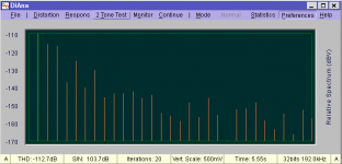
I really like to distortion analysis. This is the most useful of the software tools I have used. At this point, it would be great to have a way to use a passive notch in front and reconstruct. Would need an insertion loss curve to put in correction and some way to monitor the unnotched waveform to reference level and sync the reconstruction.
Cloud you post the schematic of (one of) your notch filter, please?
If it's a simple Twin-T, I could build one and do some tests with DiAna.
Cheers,
E.
The Shibasoku 725D is a Twin T on the first notch filter followed by two Bridged T notch filters.
The 725D and like are complete switched by very expensive relays for the tuning and level setting.
Even the AGC is relays switched in 2dB steps.
It's the closest hunk of hardware which operates similarly to DiAna. If you get a chance, it's interesting to read up on its operation.
But generally we use Twin T , passive or active, at the input to an analyzers to increase the resolution.
Nothing special.
Last edited:
Sync channel option
In the latest version, this sync channel stuff also works when the external sync option is disabled.
Also new is how outliers are treated: No need any longer to turn off the Discard outlier option, as this check is automatically disabled for the "notched" and noisy channel.
Also note the new phase tolerance items at the bottom of 2nd statistics page.
Cheers,
E.
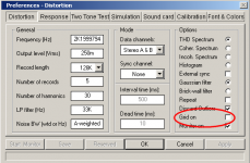
A new version is available (V1.53.4). As for the older version V1.53.2, the phase info was not yet taken into account. My apologies for this mistake.[...]
To overcome these troubles, one can use the frequencyand phaseinfo form the other "unnotched" channel. Therefore I've added a new field in the distortion preference menu (see below), where one can select the channel used for synchronization.
Note that (currently) this option is only available when the external sync option is enabled. Also note that this feature is still in development and needs more refinements
Cheers,
E.
In the latest version, this sync channel stuff also works when the external sync option is disabled.
Also new is how outliers are treated: No need any longer to turn off the Discard outlier option, as this check is automatically disabled for the "notched" and noisy channel.
Also note the new phase tolerance items at the bottom of 2nd statistics page.
Cheers,
E.
@David and Demian,
I was asking for a schematic of the notch filter in order to duplicate Demian's experiments (that is, if it's just a simple double T) and to investigate to what extent the program should be adapted to such a setup.
Cheers,
E.
I finally got inside of mine and discovered it was something from JensH. The basic circuit is pretty simple. RC Twin T Notch Filter :: Radio-Electronics.com JensH board has some switching etc. and active/passive options that help. I don't know if he has anymore. A passive one is really 3 caps and 3 resistors (and possibly 3 trimmers for tuning). I have a B&K tunable version but its a different scale of project.
I'll try to reverse engineer what I made with Jens PCB.
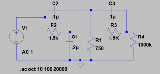
On a further note I think I discovered the magic trick B&K used on their passive notch to correct for the attenuation of the harmonics. If you raise the source impedance on the passive notch enough to get 20 dB loss at 10X the notch then the differences in the harmonic levels from ideal (-20 dB) to less than 4 dB (-4dB vs. -10 with no series Z).
Twin T
Cheers,
E.
Thanks. I will simulate this circuit and try to export the x-fer function to DiAna.The version I have was built to attempt to get a 20 dB notch. It didn't really work. I'll rebuild it as below so it's more conventional.
Cheers,
E.
Notch filter compensation
Comments invited.
Cheers,
E.
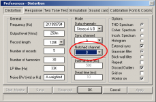
I need one more "check box" in the Distortion Preferences menu to turn on/off the notch filter compensation. At the moment, there is no room for an additional check box. But I could delete another one to make room for it. What about to remove the grid off feature (see pics)? Am I right that nobody will use this feature?[...]
I really like to distortion analysis. This is the most useful of the software tools I have used. At this point, it would be great to have a way to use a passive notch in front and reconstruct. Would need an insertion loss curve to put in correction and some way to monitor the unnotched waveform to reference level and sync the reconstruction.
Comments invited.
Cheers,
E.
Attachments
Horisontal grid lines should always be visible. So take away the tickbox.
And regarding the notch filter, the attenuation is varying with temperature, i have built several of them. So it´s very important to measure the fundamental signal before and after the twin T notch filter.
And regarding the notch filter, the attenuation is varying with temperature, i have built several of them. So it´s very important to measure the fundamental signal before and after the twin T notch filter.
I sometimes want to turn the grid off when I just want to show the shape of the residual. It's good for graphics when you are writing an article for example, and makes it look less cluttered especially with low-fi print graphics.
Can you move the grid option to the font/colors panel since it's a somewhat cosmetic option? Perhaps rename the font/color panel to Display Options or something so the user knows where to look.
Can you move the grid option to the font/colors panel since it's a somewhat cosmetic option? Perhaps rename the font/color panel to Display Options or something so the user knows where to look.
Last edited:
grid
Cheers,
E.
Also the font/colors panel is fully occupied. Perhaps a little far-fetched, but what about using the same color as the Signal background? Then the grid is also invisible.I sometimes want to turn the grid off when I just want to show the shape of the residual. It's good for graphics when you are writing an article for example, and makes it look less cluttered especially with low-fi print graphics.
Can you move the grid option to the font/colors panel since it's a somewhat cosmetic option? Perhaps rename the font/color panel to Display Options or something so the user knows where to look.
Cheers,
E.
")
Notch filter
Comments invited.
Cheers,
E.
Although it looks a bit cramped, what about an extra "combo box", where one can select the channel which will be compensated for phase and insertion loss of the notch filter? (BTW, should I call it 'Notched channel' or just 'Notch channel' ? )[..]
Can you move the grid option to the font/colors panel since it's a somewhat cosmetic option? Perhaps rename the font/color panel to Display Options or something so the user knows where to look.
Comments invited.
Cheers,
E.
Attachments
Experience tells me it's better to use more descriptive terms rather than colloquial ones as long as they aren't so awkward they have the opposite of the intended effect. Notched Channel makes sense to me.
Some programs put the title in the first entry of the drop-down box, but I do prefer a less cluttered layout to that insanity.
Some programs put the title in the first entry of the drop-down box, but I do prefer a less cluttered layout to that insanity.
I used a brickwall HP filter to get rid of hum in low-amplitude tests so they could be processed. The problem is the harmonics get shifted in phase if the corner frequency is anywhere near the fundamental. Do you think you could implement a HP filter that does not alter the phase?
HP filter
Cheers,
E.
I could implement such a filter after the signal has been FHT-ed. But I don't think that will remedy the issues you have encountered.I used a brickwall HP filter to get rid of hum in low-amplitude tests so they could be processed. The problem is the harmonics get shifted in phase if the corner frequency is anywhere near the fundamental. Do you think you could implement a HP filter that does not alter the phase?
Cheers,
E.
- Home
- Design & Build
- Equipment & Tools
- DiAna, a software Distortion Analyzer