Stop obsessing about that led. In the program I use to draw the schematic (and simulate it to double check for errors), that QTLP690C gives me 1.8v. It matches cheap 3mm or 5mm red leds, I never ever used a QTLP690C in real life.
I swear, next time I'll change that name to "red led" on the schematic.
I swear, next time I'll change that name to "red led" on the schematic.
hmm a triode loaded with css is a idea rip off?Yet another Ripped off design - this time it is the Cavalli Headwize SOHA.
well, then i should patent wheel and everybody has to pay me

This is the fourteenth thread the OP has opened on the same subject. All follow this pattern:
1. New thread: Here's a schematic I copied from somewhere, removing the copyright information and giving no attribution.
2. I want a preamp from my D/A to give me "tube sound." I have no idea what "tube sound" actually is, but I want it.
3. I have heard the word "buffer" somewhere, but I don't really get what one is or why I might/might not need one, but I'm intrigued by the word. Please spend time engineering this circuit to make me happy. I cannot tell you what it is that will make me happy, so please feel free to slap your own targets on that and debate pointlessly.
4. I will then neither bother to read and understand basic texts, nor do some experiments, nor learn how tube designs work.
5. I will then proceed to not build anything and search for the next circuit to mindlessly copy.
6. Go back to #1 with this circuit and start the process again.
Why does anyone even spend a minute doing this?
@gost22: Well the goal of a DO-it-yourself forum is that, at some point, members do stuff... which means taking out the soldering iron.
@SY: didn't catch the pattern, sorry for feeding the frenzy.
@hpeter: the rip off isn't the (very standard) cathode follower, it's the very first post.
@SY: didn't catch the pattern, sorry for feeding the frenzy.
@hpeter: the rip off isn't the (very standard) cathode follower, it's the very first post.

 ..
..


"We" ?We have a transformer with a secondary voltage 2x22V / 0.15A and 2x8V / 0.6 A, what should I change in the schematic with tube buffer?

Anyway:
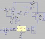
For the high voltage, use the 2x22v just as the 2x15v, tying the two secondaries in serie (read here about tying the secondaries: Transformers Part 2 - Beginners' Guide to Electronics ). You need higher rated caps though, c2-c3 must be changed to 220uf or 330uf/100v and c5-c6 to 100uf/150v. R7-R8 can be increased to 470 ohms.
For the heaters, use your two 8V secondaries in a full wave rectifier configuration, keep the rest unchanged. Read here to know what I mean: Elliott Sound Products - Linear Power Supply Design (fig. 5).
And, for the love of God, read this if you're going to mess around main voltage: Power Supply Wiring Guidelines
R=? R3=?
Is R6 = 22k; R3 = 220R remain in their value or should be changed for Usec = 2x22Vac?
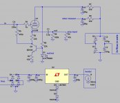
Is this good (see Figure 2)?
Thanks and Cheers!
Ben thanks for your help!"We" ?
Anyway:
For the high voltage, use the 2x22v just as the 2x15v, tying the two secondaries in serie (read here about tying the secondaries: Transformers Part 2 - Beginners' Guide to Electronics ). You need higher rated caps though, c2-c3 must be changed to 220uf or 330uf/100v and c5-c6 to 100uf/150v. R7-R8 can be increased to 470 ohms.
For the heaters, use your two 8V secondaries in a full wave rectifier configuration, keep the rest unchanged. Read here to know what I mean: Elliott Sound Products - Linear Power Supply Design (fig. 5).
And, for the love of God, read this if you're going to mess around main voltage: Power Supply Wiring Guidelines
Is R6 = 22k; R3 = 220R remain in their value or should be changed for Usec = 2x22Vac?
Is this good (see Figure 2)?
Thanks and Cheers!
Attachments
Last edited:
Where have you been chasing new ideas... If it's your first build, keep it simple. Remove that high voltage regulator, you'll add one later if you need it and if the buffer works.
R3 is still 220, R6 is still 22K. Just make sure that R6 is 2w (all other resistors can be 1/2w but it wouldn't hurt to have r7/r8 as 1w resistors).
Neither of your schematics is correct.
For the high voltage: fig.1 is correct (if the secondaries are correctly wired).
For the heaters: both are wrong. You need to tie the two 8vac secondaries to make a center tap (again, take care of the windings' phase !). Center tap is ground. Read again: Elliott Sound Products - Linear Power Supply Design , you only need two diodes.
Furthermore, why a 7812 ? the ecc88 has a 6.3V heater. Stick to my schematic, you'll make changes when it works.
- Status
- This old topic is closed. If you want to reopen this topic, contact a moderator using the "Report Post" button.
- Home
- Amplifiers
- Tubes / Valves
- "Diamond" tube preamp with 12au7