I connect mains to my amps via a globe, which prevents currents to rise too high. I set bias checking Voltage drop across emiter resistors of PTs.
I'll solder 220pF in parallel to C9 in one module today and see what happens. If it works I'll connect my test speaker and will keep it on for some time.
cheers,
Ok !But I suggest to connect the amp in series to positive side rail to watch the idle current.Not to the resistors. You check the idle current better. When you do all these ,you must wait about 15-20 min to stop rising the idle current,after that tou readjust to 250ma and wait about 10-15min.If idle current doesn"'t rise except of 3-5 ma,Check for dc offset and connect speaker.then you put your finger to the input for a second .The idle current will rise,but when you left out your finger it will come back to previous value.This is a safe and easy way I check the amps in my lab,before I connect the amps to a system.This trick will ensure that you will not have unpleasant situations later.I am technician and repair amps for 20 years .
Last edited:
Hi Aristand,
This is a fine method but I do not have a spare amperometer. I could connect the positive rail via my universal meter but it might be risky for the meter. I'll check prices of cheapest old type amperometers (non lcd display) and get one. You are right, one should have one such device.
cheers,
This is a fine method but I do not have a spare amperometer. I could connect the positive rail via my universal meter but it might be risky for the meter. I'll check prices of cheapest old type amperometers (non lcd display) and get one. You are right, one should have one such device.
cheers,
Hi Aristand,
This is a fine method but I do not have a spare amperometer. I could connect the positive rail via my universal meter but it might be risky for the meter. I'll check prices of cheapest old type amperometers (non lcd display) and get one. You are right, one should have one such device.
cheers,
You can connect and your digital multimeter in the scale of 10A or 20A.There is no problem.
Yes, I know. I have already ordered a new analogue multimeter with DC ampere meter up to 10A but I'll check if my old multimeter still works. I think my newer multimeter works up to 10A which is enough. If the old one does not work and if I get impatient I'll probably use my newer multimeter. I wonder if my modded version will work. Under simulation it shows THD below 0.00007% into 4ohm load, 10 times less than the original.
cheers,
cheers,
Last edited:
I've just got my analogue multimeter with 10A DC ampere meter.
ARISTAND,
Could you please measure voltage drop across two or three 0.22ohm emitter resistors in your amp? I wonder with 250mA idle what is the voltage drop across these resistors.
Are there notable differences between readings on different 0.22ohm resistors?
thank you,
cheers,
ARISTAND,
Could you please measure voltage drop across two or three 0.22ohm emitter resistors in your amp? I wonder with 250mA idle what is the voltage drop across these resistors.
Are there notable differences between readings on different 0.22ohm resistors?
thank you,
cheers,
I have maesured voltages 17.1mV 17.3mV and 17.4mV .This voltace drop is eq ual to 78-78.6mA per output transistor. Adding these values you have 234mA for the output stage.The rest is for the driver.The other amplifier of my friend has a conventional power supply,common for the 2 channel,Toroidal trans 750VA,4X22000MF cap.Ultra-fast hi-current diodes.As I mentined befor has the added capacitors and operates trouble-free for 6 months in a coffee-shop.Remember we must care for the stability of idle current.This is the most important factor,because instability in idle current can blown the amp very quickly.This amp measures 17.1mV 17.5mV and 17.9mV,but the idle current was stable except for the initial 15-20 min for 24 hours t0 250-252mA. You must adjust the final value of idle current after 20min.Cheers !

My own D.D Amp has the 2SC5200-2SA1987 because I had over 200 of these.So I matched them measuring their HFE by my dig multimeter.Of cource this is not exactlly the presice method but in practice gives good results.The other D.D.Amp has the transistors included in the kit.
Thanks, ARISTAND. That's how it should be. I have changed C9 to 470pF and it got a touch worse. I cannot go past 2mV across these resistors which is about 10mA. There must be something wrong with VAS.
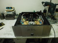
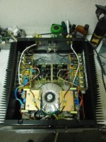
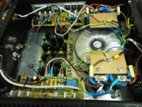
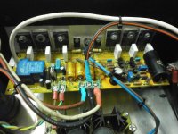
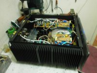
Congratulations on good work and the amp looks nice.
I use separate PS for each module. Transformers are 300VA each 2x40V plus 2x15V to feed speaker protection circuit although originally the additional winding together with 2x40V was to feed regulated PS but there is not enough room in my case.
Eeach of my PS boards has ELNA audio caps 4x15,000uF and dual 50A bridges. LTP and VAS are separately fed via additional 470uH coil filtered to the ground by 470nF cap.
thanks again,
cheers
Please check up all circuit for mistakes [ components placement,possible wrong values in resistors,or transistors on driver circuit ] As I mentioned before good thermal connection for all transistors to the heatshink is very important. What value is the dc supply.If you have soldered the output transistors,desolder these and do after the extention check adjustment as shown in the breadboard.[E.G 2.5V-2.6V Bias voltage down to 0.6-0.8V ] If bias voltage can''t be down to this value replace the 2K2 resistor with a smaller one.Solder a resistor 1K2 parallel to it and do the adjustment again. If the voltage across emitter-collector of bias transistor is over the 1v-1.3v then you have problem. The parallel combination will drop this voltage and all solve the problem.Try it and tell me. Cheers !
Thanks for the advice. Before soldering anything I checked each compomnent and have all transistors well matched. I use NJW1302/3281 as output transistors. I have no problem setting voltage drop across R3 (1k) to 2.5V. Also I set the voltage drop across
R22 to 0.5V.
I understand that you have a voltage drop across emitter-collector of Q0 (bias transistor) about 1V or less. Could you tell me exactly what is your reading there? I have to check that voltage
Could you tell me voltage drop across R27 and R29 (47k) resistors from both sides of VAS to the ground (VQ+ and VQ- on diagram).
What do you mean by parallel combination? Reducing R35 from 2k2 to 1k2?
My idle PS voltages are about +/- 57.5V at below 2mV across .22ohm resistors.
Thank you,
cheers,
You need to adjust voltage drop across C15 leads at about 0.5V not to R22.It is wrong. You will adjust at first 2.5 V and after that without output transistors connected the voltage drop to C15 or if it easy between emitter- collector of the bias transistor.Then measure DC offset. One lead between the common connection of 0.22R resistors and the other lead to ground. If you have placed the W2 trimmer you can adjust to zer therwise you don""t. I think that PS voltage for the amp is max 55V.My own has 45V for the output and 48.5V for the input. The PS in the other is 50V. Transformer windings are 2X35V and an additional 12V for the speaker protection.Check first the measurments at the pionts I suggested ,and after If you have a transformer with less voltage try it.Power transformer that can be used is 100-150VA. Remember....we repair the amp.
therwise you don""t. I think that PS voltage for the amp is max 55V.My own has 45V for the output and 48.5V for the input. The PS in the other is 50V. Transformer windings are 2X35V and an additional 12V for the speaker protection.Check first the measurments at the pionts I suggested ,and after If you have a transformer with less voltage try it.Power transformer that can be used is 100-150VA. Remember....we repair the amp.Something forgotten
As I mentioned before you will do the adjustments [ dc offset,bias voltage,2.5V without output transistors. The voltage drop across bias transistors or to C15 in this value ensures you that if you solder the output transistors then idle current will be at the min value. When you connect the transistors and you will begin the adjustment,this value will rise up,until you set the bias current. So it depents from the value of bias current. [ Larger bias-larger voltage drop ] However when you do the adjustment this value should be stable. except of few mV.Accoding to a little variation in mA to bias.
Cheers
Thanks ARISTND,
I dont't like to desolder parts unless there is no other way. So i'll try to set up things without desoldering transistors first. When I set bias to below 10mA (up to 2mV drop across .22ohm) there is no problem. Everything seems stable and I connect the amp via a 100W globe. I can do all the adjustments at such low bias if it's possible.
In simulation the amp may work at voltages well above 55V. LTP-VAS works ok even at +/-63V. Anyway, with bias current set to similar values as in your amp I should have no more than +/-53V.
I have W2 and I set it to give about 220 ohm betwen rail and emitters of Q9 and Q11. With low bias I can minimize offset. OK, so with initial bias at below 10mA I'll try to set voltage across C15 or across emitter-collector of bias transistor to below 1V. If I do not manage I'll solder 1k2 across 2k2 (R35).
I'll try to do it today after work or tomorrow.
cheers,
Janusz
Hi Artisand,
I soldered 1k2 across 2k2 resistor and without desoldering power transistors I powered up LTP-VAS section, stet up 2.5V across 1k and measured 1.28V across C15. A bit too much but PS was +/-57.3V. Then I connected PS to the output stage, zeroed offset with W2 and started setting up bias and then moving probe pulled out positive supply to VAS-LTP. I switched off the amp sa quicky as I could but R21 (220ohm VAS resistor on the negative side) was already smoking.
It didn't burn through so when desoldered it still measured 220ohm but something else must have stopped working because after replacing it and a couple of other resistors I could not set up bias current through the OPS. Turning on W3 kept increasing voltage across C15 but no current through .22 ohm on the negative side (I use ONSemi mjl1302) and oscillating current on the positive side.
So I need VAS voltages and driver transistor voltages to find out what went wrong. Looks I'm unlucky with that amp. I did not touch the other module as the first one has to be made operational. Could you please masure voltages in VAS and OPS in your amp? Voltage drop across Collector-Emitter of each transitor and 47k in VAS to the ground. One side probably will do as VAS and OPS are symetrical so voltage drops should be roughly the same.
Thank you,
cheers,
Last edited:
I can"t help you because I am on holidays.But I think that you burn the driver transistors and if you are unlucky some of the output.To check this measure with your multitester [ in diode function ] between emitter-collector all these transistors [ out-driver] if you read zero are blown.When you adjust the values [ idle,offset,2.5v] are your transistors mounted on the heatshink ? The voltage between 220R leads slould be 0.6-0.7V under 2.5V and 3.6-4.2V under the supply voltage to the leads of 47k resistor.
Cheers
ARTISAND
Cheers
ARTISAND
Thanks ARTISAND,
Yes, all my transistors are on a heatsink. My suspicion is that Q18 is blown. There is a chance that some transistor/s in VAS are not working properly because with only LTP-VAS powered up I was gettning almost 1.3V acrosss C15.
Power transistors I believe are OK as PS was going through a globe and it was dark all the time. I'll also check bias transistor. I have a transistor tester which usually works on transistors in circuit. I have plenty of transistors so replacement is not a problem. I also could try replacing them with mosfets as these give very low phase shift.
cheers,
Very dangerous for the circuit to read 1.3V across C15. this is the reason I suggested to solder the parrallel resistor.To experiment with mosfet is not bad idea , but you will replace 10R resistors by larger values 220-330R recommented.I have a module to experiment and I tried Hex-fets [ IRFP9240-IRFP240 ] I replaced the 220pf cap with larger value,and solder it to the negative side,May be it works better and now. Try this , no problem ! but you must desolder the existing capacitor.The module with hex-fet is working at 42V with 600mA.Fantastic sound ! similar to tubes.
Hi ARTISAND,
I meant to use mosfets for drivers only (q17 and q18) and jfets to replace q9 and q13. I simulation it gives vary low phase shift.
I soldered 1k2 across R35=2k2 and got almost 1.3V with LTP-VAS powered but no power to q0 (bias transistor) as this is powewred up together with OPS. That's why I suspect that there must be something wrong with VAS as that 1.3V is a voltage drop between collectors of q10 and q12.
cheers,
- Status
- This old topic is closed. If you want to reopen this topic, contact a moderator using the "Report Post" button.
- Home
- Amplifiers
- Solid State
- DIAMOND DIFFERENTIAL INPUT POWER AMPLIFIER EBay kit