Diamond v1.2 JIM AUDIO
Thanks AndrewT,
Well, I know Stanton Tin nearly a year, I've acquired several amps, including the excellent lateral MOSFET with Mimesis - an amazing sound, very detailed. Use in multi amplified. I had some difficulties and Stanton helped in the solution.
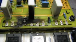
He also said it has sold some cards and work successfully. It seems obvious that does not reveal names, but I prefer to believe it. The worst has happened tonight, trying to measure voltages, burned resistors of 10 ohms. There may be a mistake on my mount, I can not close the door without waiting for a solution.
But it seems fitting that this hobby is interesting precisely the challenges of overcoming problems.
Thanks AndrewT,
Well, I know Stanton Tin nearly a year, I've acquired several amps, including the excellent lateral MOSFET with Mimesis - an amazing sound, very detailed. Use in multi amplified. I had some difficulties and Stanton helped in the solution.
He also said it has sold some cards and work successfully. It seems obvious that does not reveal names, but I prefer to believe it. The worst has happened tonight, trying to measure voltages, burned resistors of 10 ohms. There may be a mistake on my mount, I can not close the door without waiting for a solution.
But it seems fitting that this hobby is interesting precisely the challenges of overcoming problems.
Attachments
Joint of RF1 and RF2 (nfb resistors) should be connected to gates of Jfets Q4 and Q6. Resistors R22-23 float emiters of Q17-18. That's how it should be. You may connect the joint of RF1-2 to a joint between R22-23 (this track is cut on the board to prevent that connection which originally was on) but it's not the best configuration. Floating Q17-18 is better but you may try the other but it's not likely to solve the problem.
The problem I had was setting bias - once current through output emitter resistors 0.22 exceeded 10mA it started to climb so there was no stability. Hence, it's necessary to redesign bias circuit and possibly VAS. LPT also can be somewhat changed. I haven't yet finished that step. Maybe thiis weekend.
Problem is that on simulation it works but only just.
cheers,
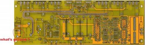
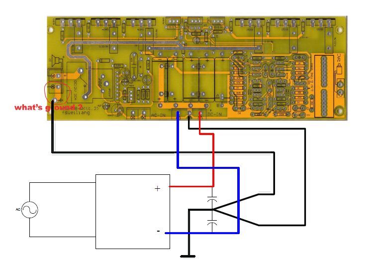
proper ground connection
There is a node ( and a big PTH hole too)label with ground symbol on the board. This is not an omission in PCB layout, but a prevention of large current flowing into the signal ground.
In any case, proper connection has to be like this, nothing fancy though.
There is a node ( and a big PTH hole too)label with ground symbol on the board. This is not an omission in PCB layout, but a prevention of large current flowing into the signal ground.
In any case, proper connection has to be like this, nothing fancy though.
I appreciate the remarkable effort of Mr. Stanton Tin - were many e-mails, dozens of pictures and measurements and an accident that burned up NJW0281G transistors.
Why is this:
To understand what seems simple: many buyers know amplifiers soldering kit and assemble electronic devices, know basic electronics, as is my case. Others, as we see here in this forum are knowledgeable deep, some designers and deal with these problems with ease.
What's the solution then?
Improve the documentation provided in the sales kit, complete with layout and instructions for assembly and biasing. Salespeople need to understand there are many different types and levels of knowledge of purchasers of boards amplifier kits.
I said several times that it had no audio output, a simple matter to designers, however, cost for me to take time and many still burn a card. It is a suggestion for improving the documentation provided.
Apologies for my bad English: I use google translator.
Thanks again
Is your working now?
You do not have to wire PS/case ground to the speaker ground on the board and then to the speker socket ground. I wire PS ground directly to the speaker socket ground.
I have soldered the modded configuration on one board (the other is still original) but have not yet powered it up.
cheers,
You do not have to wire PS/case ground to the speaker ground on the board and then to the speker socket ground. I wire PS ground directly to the speaker socket ground.
I have soldered the modded configuration on one board (the other is still original) but have not yet powered it up.
cheers,
Working Diamond Differential v 1.2
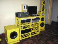
Yes Janusz, is working 100%, on a test bench with a small speaker. I mount the chassis (case) in an old amp (Gradient HA-II) and powerring subwoofers Peerless 830452 in a multi amplified system.
Curious: For zero offset need to remove W2 and R28 and replace R16 220 ohms. A board A was 0.3 mV and B a 1.5 mV. With the trimpot was 17 mV.
Another very controversial issue: this star ground board. If the hole to weld with the ground symbol is available, because the designer did not like the other 99.99% by integrating the ground on one bus. According to the manufacturer Rane - A version of this RaneNote was published in the Journal of the Audio Engineering Society, Vol. 43, No. 6, June, 1995. Complete in Grounding and Shielding Audio Devices
"Chassis Ground vs. Signal Ground - Let us examine the distinction between chassis and signal ground in audio devices. Chassis ground is generally considered any conductor which is connected to a unit’s metal box or chassis. The term chassis ground may have come about since units with 3-conductor line cords connect the chassis to earth ground when plugged in to a properly wired AC outlet. In units with a 2-conductor line cord (consumer equipment), the chassis does not connect to earth ground, though the chassis is normally connected to the signal ground in the box in both unbalanced/consumer and in balanced/pro equipment. Signal ground is the internal conductor used as the 0 V reference potential for the internal electronics and is sometimes further split into digital and analog ground sections. Further signal ground splits are also possible, though it is important to remember that all “divisions” of signal ground connect together in one place. This is usually called a star grounding scheme. It is easy to confuse chassis ground and signal ground since they are usually connected together — either directly or through one of several passive schemes. Some of these schemes are shown in Figure 3. The key to keeping an audio device immune from external noise sources is knowing where and how to connect signal ground to the chassis. First let’s examine why they must be tied together. We’ll cover where and how in a moment. There are at least two reasons why one should connect signal ground and chassis ground together in a unit. One reason is to decrease the effects of coupling electrostatic charge on the chassis and the internal circuitry. External noise sources can induce noise currents and electrostatic charge on a unit’s chassis. Noise currents induced into the cable shields also flow through the chassis — since the shields terminate (or should terminate) on the chassis. Since there is also coupling between the chassis and the internal circuitry, noise on the chassis can couple into the internal audio. This noise coupling can be minimized by connecting the signal ground to the chassis. This allows the entire grounding system to fluctuate with the noise, surprisingly providing a quiet system. Further coupling reduction is gained when the chassis is solidly bonded to a good earth ground — either through the line cord, through the rack rails or with an independent technical or protective ground conductor. This provides a non-audio return path for any externally induced noise. The second reason to connect signal ground to chassis is the necessity to keep the signal grounds of two interconnected units at very nearly the same voltage potential. Doing so prevents the loss of system dynamic range where the incoming peak voltage levels exceed the power supply rails of the receiving unit. Unbalanced units connect successive signal grounds together directly through each interconnecting cable — the sleeve of each RCA cable. This, and the fact that the chassis is generally used as a signal ground conductor, keeps the signal ground impedance of unbalanced systems very low. Many may agree that unbalanced systems are helped by the fact that the chassis are normally not earth grounded. This allows an entire unbalanced system to float with respect to earth ground. This eliminates the potential for multiple return paths for the audio grounding system, since there is not a second path (ground loop) through the earth ground conductor. Low signal ground impedance between units is essential for acceptable operation of all non-transformer-isolated systems, balanced and unbalanced. The design of balanced interconnection does not connect signal grounds directly together. The negative conductor provides the required signal return current.
To avoid loss of dynamic range, balanced systems use a different method of keeping signal ground potentials small. "
You know what were the changes between versions 1.2 and 1.4 or who designed / manufactured to clarify?
Thank you for your valiant effort to help beginners like me as well as others who helped. What would be simple for designers and experts became a serious problem: a board burned all the powers OnSemi and almost all components of the output. Regrettable.
I do not think there are any notable changes between v1.2 and v1.4. The one I know is that there is no speaker ground on the board. I have R2 and R13 changed to 47k
from 33k. I have also separated input signal ground from the dirty ground by a small resistor pralelled in both directions with diodes. To do this I cut the thin track on the board.
These are practically all changes I did. The additional mods are to stabislize bias. If they work or not I'll se when they are done. Maybe I have to ask Stanton again why my amp behaves so strangely if your is working ok.
It's interesting that yoyu had to remove W2 to lower the offset.
Theoretically, setting W2 to such a value that R28, R16 and W2 are 220ohm should give the same result.
cheers,
AndrewT,
The scope of this article Rane on how to eliminate hum in unbalanced system. Therefore considerations about the importance of unifying two ground models, the low level at the entrance and the ground board, just what has no connection at Diamond Diff, in version 1.2. I may have misunderstood, but modern systems of amplifiers do not use two separate earthing systems. The ground amplifier should be only one strong track. In the figure shown by Tin Stanton suggests something similar star ground connecting the speakers in the PSU, it can form causing ground loop hum.
Janusz,
I have in depth knowledge to treat the mods. But I did a test by changing W2, the two extremes. Should associations series / parallel range from 165 to 236 but these cards came up in 194 ohms, so it apparent offset of 17 mA.
I have builded this amplifier with success for the first time.It works 3 months without problems,and it sounds great great.The input and the output stages have indepented r power supply.But for the input stage is regulated.For this modification I remove the 33R resistors.I have also isolated the input ground with 10R resistors.Now for these who doesn"'t finished the amplifier yet I suggest to be patient.Check up all the circuit , all the mechanic construction ,thermar connection between all transistors with heatshink.If that all are good and the idle current doesn"'t stop rising connect a capacitor parallel with the 220pf from the copper side.The value is between 100-220pf.The wiring of the speaker ground can be with a wire from the negative output connector to the central point of supply.As i told before my amplifier works. I have set the idle current to 350ma Supply voltages are 48 volt for the input stages and 45 volt for the output.
Aristand,
Which cap are you talking about? Is it C9 connecting the collector of Q10 to the ground paralelling R27 (47k)?
So increasing C9 value to 330pF - 470pF would stop bias current rising?
Thank you,
cheers,
Yes the value of original capacitor is 220pf.You can solder a capacitor from the copper side parallel to it"s legs. My own amp didn"t need it , but I placed to another amp of a friend.The value was 330pf for the left chanel and 470pf for the other.After that it was no problem,the amplifier operated perfectly.Try to connect capacitors from 100-470pf parallel .The right value stops bias rising.
Yes the value of original capacitor is 220pf.You can solder a capacitor from the copper side parallel to it"s legs. My own amp didn"t need it , but I placed to another amp of a friend.The value was 330pf for the left chanel and 470pf for the other.After that it was no problem,the amplifier operated perfectly.Try to connect capacitors from 100-470pf parallel .The right value stops bias rising.
You can see this trick in various amplifiers.Some designer put this capacitor to the negative side,other use a resistor in series with this cap.All these tricks are used for the same purpose.
Thanks Aristand,
It's the first time I have encountered problem of self-rising bias current. Anyway, I added caps as part of the redesign between VAS and LTP and considered increasing values of the small ones in VAS but I haven't yet powered up the module.
On simulation it does not show up and the amp works OK but only just. Very sensitive to the quality of PS powering VAS. That's why I considered using regulated PS for LTP and VAS as you did but it's difficult to fit it in my case.
I talked to Stanton about that problem but he did not come up with that advice. Now I have a number of different versions of this amp in LT spice all working except for one (which sometimes works and sometimes not!!!) but the original also worked. That is the problem with simulation. If it shows that amp does not work it does not work but if it works in simulation then maybe it will work in reality.
cheers,
Thanks Aristand,
It's the first time I have encountered problem of self-rising bias current. Anyway, I added caps as part of the redesign between VAS and LTP and considered increasing values of the small ones in VAS but I haven't yet powered up the module.
On simulation it does not show up and the amp works OK but only just. Very sensitive to the quality of PS powering VAS. That's why I considered using regulated PS for LTP and VAS as you did but it's difficult to fit it in my case.
I talked to Stanton about that problem but he did not come up with that advice. Now I have a number of different versions of this amp in LT spice all working except for one (which sometimes works and sometimes not!!!) but the original also worked. That is the problem with simulation. If it shows that amp does not work it does not work but if it works in simulation then maybe it will work in reality.
cheers,
My first amp worked for the first time without problems.powered with a conventional power supply.After that I listen the amplifier for 3 weeks and I was very pleasant with the sound.After that I decided to improve this with the regulated supplies.The other amplifier works with the capacitors added,and has a conventional power supply.Power the amplifier with a amperometer in series adjust the idle current to 250ma and watch it.After 15-20min you readjust it to 250ma.From that time the idle current does"t rised up except of 3-5ma.I watched the amp for 2 hours without any problem .After that I connected the speakers ...and I listened ....beautiful music.
I connect mains to my amps via a globe, which prevents currents to rise too high. I set bias checking Voltage drop across emiter resistors of PTs.
I'll solder 220pF in parallel to C9 in one module today and see what happens. If it works I'll connect my test speaker and will keep it on for some time.
cheers,
I'll solder 220pF in parallel to C9 in one module today and see what happens. If it works I'll connect my test speaker and will keep it on for some time.
cheers,
- Status
- This old topic is closed. If you want to reopen this topic, contact a moderator using the "Report Post" button.
- Home
- Amplifiers
- Solid State
- DIAMOND DIFFERENTIAL INPUT POWER AMPLIFIER EBay kit