Hi,
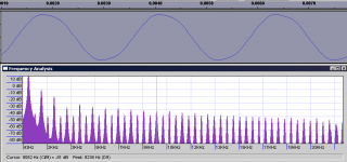
I have just replaced some transistors, resistors, and diodes on my musical fidelity synthesis that I blew up, and it works, which is a surprise. The disappointment is that it works crappily. There is a good deal of the second harmonic in everything I play, and I looked at the waveform, and found it isn't a pure sine wave any more. One problem could be that i replaced some transistors with different hFE transistors, while some where not replaced. Can someone help me diagnose my problem? Thanks. I've attached a frequency spectrum and a waveform.
I have just replaced some transistors, resistors, and diodes on my musical fidelity synthesis that I blew up, and it works, which is a surprise. The disappointment is that it works crappily. There is a good deal of the second harmonic in everything I play, and I looked at the waveform, and found it isn't a pure sine wave any more. One problem could be that i replaced some transistors with different hFE transistors, while some where not replaced. Can someone help me diagnose my problem? Thanks. I've attached a frequency spectrum and a waveform.
Attachments
more details...
I had to replace a micro electronics bc414c with a fairchild bc550c. I also replaced a bc416b with a fairchild bc560b. Also, I replaced the output and driver stages, the outputs were 2sK226/J82 and they were replaced by 2sK1058/J162. The drivers were 2sB648A/D668A, with the marking B on them, which I think were the gain category. They were replaced by the same model, but the marking C, so I think they are in a different gain category. I also replaced a 100R resistor, two 1n4148 diodes, and a 4.7v zener diode. Any help anybody can give will be greatly appreciated.
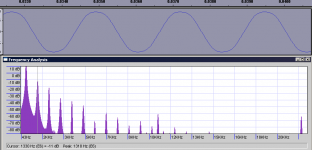
The first pic I posted was of the output with a speaker load. This one is without load.
I had to replace a micro electronics bc414c with a fairchild bc550c. I also replaced a bc416b with a fairchild bc560b. Also, I replaced the output and driver stages, the outputs were 2sK226/J82 and they were replaced by 2sK1058/J162. The drivers were 2sB648A/D668A, with the marking B on them, which I think were the gain category. They were replaced by the same model, but the marking C, so I think they are in a different gain category. I also replaced a 100R resistor, two 1n4148 diodes, and a 4.7v zener diode. Any help anybody can give will be greatly appreciated.
The first pic I posted was of the output with a speaker load. This one is without load.
Attachments
schematic
I've been trying to draw out a schematic of it... I'm not too good at that, so it's been very slow going. I got confused around the 6th transistor. i have pics of the board and copper tracks underneath. Will those suffice? Sorry for the non-help... The pics of the board are too large to fit in an attachment, but I can email them if you'd like.
Part of it may be the method with which I blew the channel. I shorted a resistor lead, which I think was a base resistor, going from -62v to a wire jumper, which I think goes to ground. This popped the case off of a bc414c and two 100R resistors caught on fire. I replaced the components that looked bad, and started it up again, to find out that I really didn't fix the problem, I just added things to catch on fire again. By now, I was taking components out and testing them. Found out a lot of the components were fried like chicken.
One more thing, I didn't replace one bc416b. I left that one in there. Could this be the culprit?
when the case says bc416b does it mean that the gain category is b? or does it mean something completely different? Thanks.
the micro electronics data sheets are here
The fairchild 550/560 are here
I've not been able to find data sheets for the 648a/668a transistors, but I found this:
http://www.datasheetarchive.com/datasheet/pdf/1317.html
It plays music... dunno which component would be faulty. I'm a novice, but I took basic circuits in my undergrad. Could it be a diode that needs to be replaced? aargh... I should go to sleep. Please help me, I'd really like to keep this guy around. Thanks for the suggestions so far.
I can listen to it, it just sounds ugly with some passages.
I can listen to it, it just sounds ugly with some passages.
when the case says bc416b does it mean that the gain category is b?
Yes.
One more thing, I didn't replace one bc416b. I left that one in there. Could this be the culprit?
Maybe. Simply replace it.
You can also measure the voltages from the left & right channel and compare them. Maybe an electrolytic is faulty.
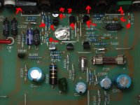
Here's a top-down view. There are also three diodes behind the green transistor on the right. I replaced two of those. This is the right channel, I worked on the left. Could I have missed a dead diode? I'll check it tomorrow. right now, I should go to bed. Thanks for the help.
I didn't put an arrow on one of the diodes I replaced. D9 was also faulty. it's to the left of ZD1 on the left side of the picture.
Does anybody want a picture of the bottom tracks?
Thanks for the help.
So, I guess that I replaced the transistors with the right replacement transistors? I sure hope so. Could it be crossover distortion that is messing with the waveform? Thanks.
Attachments
The BC's wouldn't cause so much problems but the mosfet's are more sensistive. If you could do some reverse engineering and make a schematics and also dig up datasheets for the transistors you have replaced maybe we can see something. I suspect lack of suffient feedback, very different Vgs or lack of bias.
do people want a flac of the waveform? that isn't so hard to do. I found the data sheet for the K226 on a different thread (to which I also replied).
http://www.diyaudio.com/forums/showthread.php?postid=707369#post707369
Could it be the input cap? it looks a little juicy under there... C30.
http://www.diyaudio.com/forums/showthread.php?postid=707369#post707369
Could it be the input cap? it looks a little juicy under there... C30.
If you replaced the output devices you most probably have to re-adjust the quiescent current in the output stage. You should measure it in the original channel and try to set the new channel to the same value. Is the new channel appreciably warmer or colder on the heatsinks than the orig channel?
Jan Didden
Jan Didden
Quiescent Current:
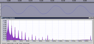
I have adjusted this, but actually, no matter how it's set, the problem still occurs. Right now, the HS is about the same from right to left. If this were the case, wouldn't the distortion be at the crossover point? I think the problem is not getting the right slew rate on something. It seems that on the sine wave, going up the curve is a higher slope and then it kind of crests a bit and slows down.
Also, this problem happens at all volume levels. I think I forgot to mention that. Could that be indicative of a faulty buffer stage? Thanks for the help you guys.
-Phil
One more thing:
Why would they use a b gain on one transistor and use c gain on its complimentary?
My plan of action is to replace C30 with a non-electrolytic cap. Is this foolish? Also, I will replace the rest of the diodes, since I have some on hand. I will also replace the 416 that I left in there. If this doesn't work, then I'm at a loss.
bad joint? like cold solder? I've tested continuity on all my solder joints, they are all good. I've not had the time yet to replace the transistor. I see there's 4 diodes going from the base of a driver to ground, and I only replaced 3 of those. I think the other one was ok, but I will definitely replace this last one in series. There is a zener that I think I missed too. Amazing that it works with dead components. I'll check my solder joints again, and see if that turns anything up. Thanks. Perhaps I'll have time tonight to do that. if not, I'll just listen to crappy sounding music tonight.
-phil
what makes you guys think these things? common problems? Or are you looking at the waveform and thinking about what may cause those issues? I'm working on the schematic, so that may be up in a day or so.
-phil
what makes you guys think these things? common problems? Or are you looking at the waveform and thinking about what may cause those issues? I'm working on the schematic, so that may be up in a day or so.
- Status
- This old topic is closed. If you want to reopen this topic, contact a moderator using the "Report Post" button.
- Home
- Amplifiers
- Solid State
- Diagnose my problem? Replaced transistors and now high THD