I think the traces are really thin gauge copper. I just don't want to admit that I'm a neanderthal with a soldering iron. of 15 replaced components, I've lifted 9 pads. My solder sucker is small though. I should probably get a big one, or, just hook a shop vac to the current one's nozzle. that could work...... diy solder sucker....
I just don't want to admit that I'm a neanderthal with a soldering iron
Yes, it seems so...
")

I've lifted 9 pads. My solder sucker is small though. I should probably get a big one, or, just hook a shop vac to the current one's nozzle. that could work...... diy solder sucker
Yeah. Well, these soldering irons from Weller aren't chep but worth the money. My first one's still alive and more than 15 years old. Use the analog ones not that crappy digitals.
the lifted pads problem was solved, but still, distortion.
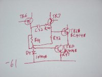
One diode was dead in the series of 4 going from TR13. Also, I replaced the BC416 that was still in there with a BC560.
I think it's one of the A1085's from the differential input pair, probably TR7?
Maybe if I describe the sound I'm hearing, it'll work better for you to pinpoint the problem. The sound is like a rattling, like as if you put a piece of paper over the driver of the speaker and it's buzzing with certain frequencies. It's very prominent with piano music. Chopin never sounded hairier. It's almost like someone left the snare drum's snares on and set it in front of the speaker. It's bugging me, so I'm only listening to the right channel now. Any more advice?
Does my schematic look weird? If the base of TR8 is connected to R44 and the then to the base of TR12 and 13 what does this do? I'm kind of confused as to the function of that design. Any enlighteners?
only source I can find (with a quick search, of the sites I know) is here in Aus at http://www.rsaustralia.com do a search on 2sa1085 on the main page, it is session based so I can't put in a link.... the one that have doesn't have the e suffix... they are expensive little trannies!!! $1.87 each makes matching them a somewhat expensive excercise!!
Tony.
Tony.
Thanks for the link. I'm in the US and shipping 5 dollars worth of transistors across the ocean doesn't quite seem like it's very cost effective. Anything in north america? audiolabga.com says they stock them but they're backordered. Don't know how long they'll take to source them, but for now, I'll be listening to one channel.
so....
a few months later, it's still ugly sounding, and more ugly looking. I replaced input cap C30 and coupling cap C33, all 2sa1085E transistors, and it still sounds pretty crappy. I replaced C30 and C33 with 100uf electrolytics.
any other ideas? the pot RV1 has no effect on the distortion. Should I just take it in to a shop? I'm sick of using headphones. Thanks.
Sorry to check in so late in this thread (missed it until now), but looking at the fft of your 'correct' channel in the first few posts, that seems pretty crappy too; there is not too much difference between the 'good' and the 'bad' channel. I have a distinct feeling you have some measurement anomaly also. If that is the case, no matter what you replace, the results will remain crappy (at least on the measurements) and it is difficult to find the way to go.
Can you elaborate on your fft measurement? What signal level, frequency, load, measurement equipment/sound card?
Jan Didden
Can you elaborate on your fft measurement? What signal level, frequency, load, measurement equipment/sound card?
Jan Didden
ha...
there doesn't look to be much of a difference, I know, but there is a big difference in the sound.... however that works I have no clue. It sounds like there's a snare drum with the snares left on in front of the speaker.
my measurement system was pretty much a hack. I ran the input from my outboard m-audio usb quattro, which went through the integrated preamp, and then through the amplifier section. The input for the data was from a 1/4" to RCA adapter with a test probe stuck in the center hole, then the other end of the test probe was touched against the output terminal of the amplifier. I think the input was clean. It's easier to see the discrepancy with the waveform, as you can see a crest on the sine wave. I don't recall what kind of windowing I used. It's on a linear frequency scale.
I've gone through and re-soldered some of the joints that looked like they might have been bad, but nothing changed.
to really diagnose where the problem is, I need an oscilloscope. or, I need a technician to tell me what the problem is, and then fix it for me. Any more ideas for fixing it? Thanks.
philibuster said:ha...
there doesn't look to be much of a difference, I know, but there is a big difference in the sound.... however that works I have no clue. It sounds like there's a snare drum with the snares left on in front of the speaker. [snip]
Yeah, both channels have a LOT of 3rd harmonic distortion visible on the waveform. Whatever the problem on the bad channel, it's also on the good channel. So, possibly the problem is not caused by the replacements you did in the one channel, so it would not help to look in that area. Let me think...
philibuster said:[snip]I need a technician to tell me what the problem is, and then fix it for me. Any more ideas for fixing it? Thanks.
You need a schematic so a technician can think about the possible problem...
Jan Didden
It is quite hard to diagnose a problem from "it sounds crappy", especially since both channels measure almost the same. There's a distinct chance that the problem isn't in the amp at all.
Have you tried switching speakers between channels to eliminate the possibility that one speaker was damaged when the one channel blew up?
Jan Didden
Have you tried switching speakers between channels to eliminate the possibility that one speaker was damaged when the one channel blew up?
Jan Didden
Looking at the amplifier a third time... I posted an incorrect schematic. A correction is attached.
I have made every channel combination, including switching input from the sound card, and the speakers. Every time, it's the same amplifier channel that sounds bad.
When the amplifier does not have an input signal, the output is quiet. The distortion increases linearly with input amplitude. The output has 5 mV offset. The distortion happens all the time, and never cuts in and out if components are pushed on.
What does a faulty input coupling cap sound like? What if the feedback decoupling capacitor C33 is bad? would that cause distortion like I'm hearing?
Sorry this is so tedious. Thanks for your help though.
Attachments
philibuster said:Looking at the amplifier a third time... I posted an incorrect schematic. A correction is attached.
[snip]Sorry this is so tedious. Thanks for your help though.
These things are never easy. I think a methodological approach would be to do an fft of the feedback signal applied to the right hand base of the input pair (use a series resistor of say 1k to the test probe so as not to upset the stability). Comparing the good and bad channel should give an indication whether the open loop gain and feedback system is actually working. We can go on from that.
But first the measurement system should be validated by measuring the input signal, that should be nice and clean.
And it would also be helpfull to have a complete and updated schematic available. I know, all these things take time, but groping around in the dark will take even more time, with little chance of succes.
Jan Didden
It works now...
I replaced the coupling caps with... wire jumpers. Sounds just fine, but I have 500mV dc-offset on the load. It makes the cone jump back a little when it's turned on. I've tried many different types of capacitors, but they all sound really horrible. Everything sounds like its low-frequency is rolled off really high. The coupling caps were 100uF electrolytics before. I wonder if they had such large coupling caps put in there because otherwise the bass would suffer. Any ideas? What do you think is a reasonable value for the coupling caps? 3-4uF? 10? 100?
With the wire jumpers, the bass is crazy good. The distortion is gone. But that stupid DC-offset is killing me.
Anyway, it sucks to replace every diode in the board, lift about 15 traces, replace every transistor in the board and find out it's just the coupling caps... Well, I guess the transistors were fried anyway, and the output devices were toast as well.
- Status
- This old topic is closed. If you want to reopen this topic, contact a moderator using the "Report Post" button.
- Home
- Amplifiers
- Solid State
- Diagnose my problem? Replaced transistors and now high THD