Seem You miss-match cathode resistor with anode load resistor? Dissipating power at the R katode is much much smaller than at the anode load R... Enough for expertiseYes indeed - I regularly parallel up cathode resistors in filament bias. That's how you do it. As I said, you also put these big cathode resistors outside the chassis because they get very hot.
12.5mA at 22V Pd=0.275W thermal dissipation - does not need even heatsink if You use 1W or 2W standard resistor...

same 12.5mA at 10K anode load Pd=1.5625W so if You put 10W power resistor there will be only slight warm.
.
Same consideration for say -50V Ug and 35mA for the cathode resistor giving Pd=1.75W, with 7W or 10W standard power resistor
there is NO need to put Rk external position far from tube...
Anode R load of say 4700 ohm with same 35mA wil dissipate Pd=5.75W. That is might look a like huge BUT with only 23W that load wil be only slight warm. And without heatsink too... It could be made of 10 x 47K 3W-5W resistors, probably just few degres from body temperature...
.
It is not a big problem at all, many people (including myself) did this many times.
.
So "Your construction" for the DHT supply is actually copy-paste implementation of other people finished and tested product?I have on several occasions explained how to construct a DHT stage in filament bias. Why - do you want to know how to do it? Start by looking at Rod Coleman's site Lyrima and study everything about his regulators and filament supplies. He supplies a lot of his regulators for those who build stages in filament bias. Buy a couple of his V9 regulators and try out a build with something simpler like a 2P29L. Look at Ale Moglia's site Bartola valves for plenty of designs. He uses active loads, I use resistor loads but the filament supplies are the same.
Thanks...
But off-course - You have made several DHT 10Y, 45 ets designs and You simply know how to design with special skills...
Last edited:
This is completely hopeless - you are beyond help. My designs are my own. When speaking of Ale Moglia he is a good friend and it was actually me who introduced him to DHTs. It's the other way around. You are malicious, ungrateful, devious and I don't see any point in any of us trying to help you with anything given the responses we get from you. These posts just clog up the thread with unnecessary rubbish and I'm not going to add to them any more. If anyone else wants to continue arguments that go nowhere that's up to them. For my part I consider you a troll and I have nothing else to add.So "Your construction" for the DHT supply is actually copy-paste implementation of other people finished and tested product?
Thanks...
Last edited:
You said this tooThis is completely hopeless - you are beyond help. My designs are my own. When speaking of Ale Moglia he is a good friend and it was actually me who introduced him to DHTs. It's the other way around. You are malicious, ungrateful, devious and I don't see any point in any of us trying to help you with anything given the responses we get from you. These posts just clog up the thread with unnecessary rubbish and I'm not going to add to them any more. If anyone else wants to continue arguments that go nowhere that's up to them. For my part I consider you a troll and I have nothing else to add.
Based on that - You are using R.C. DHT regulator? Like all other people ordered and payed for the device?I have on several occasions explained how to construct a DHT stage in filament bias. Why - do you want to know how to do it? Start by looking at Rod Coleman's site Lyrima and study everything about his regulators and filament supplies. He supplies a lot of his regulators for those who build stages in filament bias. Buy a couple of his V9 regulators and try out a build with something simpler like a 2P29L. Look at Ale Moglia's site Bartola valves for plenty of designs. He uses active loads, I use resistor loads but the filament supplies are the same.
I just want to know what is Your contribution to famous DHT? What is this Your design? Maybe the soldering few solder points? Or choosing the few other passive components (with wrong values) to make triode circuit working?
.
Please note that You are using "words" like:
"You are malicious, ungrateful, devious and I don't see any point in any of us trying to help you with..."
You said all of this just because I noted, with the arguments, to the mistakes in Your "design",
happy listening...
Nice to see the plate characteristics for 6C4C/6S4S.. So, if the input to the preamp is 3v (or 4v or 5v) P-P what is the problem with a design point in the area that you show? And then the question, how does it sound? It is NOT out of the linearity region...that does not happen until below 7 or 8 mA, and for this, it's never a possibility. Who gives a flying flip about "too small Anode voltage, and very small current"?this is the static settings graph from schematic #94. Showing that the tube are out of the linear region, too small Anode voltage, and very small current.
Best, Robert
Three versions are available, outcome is that all of these 3, visualy different, are the same after scaling...Nice to see the plate characteristics for 6C4C/6S4S..
I did not cemented input signal value...So, if the input to the preamp is 3v (or 4v or 5v) P-P what is the problem with a design point in the area that you show?
?And then the question, how does it sound?
Yes it is out of the linear region + insanely under-voltage + irrationally under-current.It is NOT out of the linearity region...that does not happen until below 7 or 8 mA, and for this, it's never a possibility.
It could be seen on factory chrs. graph and factory tube datas
One (the beginner seduced with wrong information and advertising) who will build these version, and made new one for compare, to the proper and reasonably technical design?Who gives a flying flip about "too small Anode voltage, and very small current"?
...
It is a fact and truth, all of You that took personally, notes about something else that is not personal, and offended me in public domain, just because i said some truth about few-element "design", simply could not change these facts regardless of amount of force, irony, cynicism and textual-public-mob oppression...
Last edited:
If read the thread you understand why it's not the same. I cannot see mistakes but choices that are not yours. Since the tube will work pretty much linearly even at low current for the desired swing all your rant is unnecessary. We all know the difference between the 2 operation points in this 3d because have already been there. I can actually say that the simulator Euro21 has posted a bit earlier is pessimistic about distortion....in real life is quite less! THat simulator does not work well for small signal in power tubes regarding distortion..
Same consideration for say -50V Ug and 35mA for the cathode resistor giving Pd=1.75W, with 7W or 10W standard power resistor
there is NO need to put Rk external position far from tube...
It's not the same working at 50 bias and there is a reason for having the resistors out: possibility to change/swap them fast if want to implement filament bias. Filament bias with 50V drop with 1.035A current means 53.5 VA dissipation and quite larger resistor wattage required. 15V drop is 3.5 times less. Quite a difference!
Last edited:
Hello - good to hear from you! In terms of bias for these large DHTs you can see from the photos of working 10Y and 46 stages that even with around 10V bias the cathode resistors, and the heatsinks for Rod Coleman's regulators, are large and get very hot. You can see the discolouration on the Russian military resistors in the cathode due to the heat, and you can see why they need to be mounted outside the chassis. It would be the same with a 6C4C. The heatsinks I've used are the minimum size - they get hot to the touch but not burning hot. A bias of around 10-12V suits the 10Y best. The 46 and 6C4C are outside their usual operating points but still work fine and sound good. These are the compromises I've talked about with filament bias. If you increased the bias you would need bigger heatsinks and cathode resistors and a bigger filament transformer - the filament supply is in a large external box. So it's easy to see the practical limits you work with by using a 10Y, 46 or 6C4C. Taking up the bias voltage much beyond 10V would give you a monster of a boat-anchor - just not a practical design. As built these stages sound very good indeed. In my case they are the drivers for the 2a3 outputs, and I use a Hammond 1140-LN-C SUT in 1:4 to increase the gain. The 10Y has a mu of 8 and is my regular stage. The 46 has a mu of around 5.6 so could really do with 1:5 SUT or more. The 6C4C has a mu of just over 4 so needs an even bigger SUT ratio, but it would make a nice preamp stage because of its low Ri. It sounded very good with a cathode bypass cap and, like the 10Y and 46, would sound better still in filament bias. Filament bias is cleaner and more detailed. Pics below. The 46 stage was just an experiment, and the modular chassis shows this, but it does in fact sound excellent.It's not the same working at 50 bias and there is a reason for having the resistors out: possibility to change/swap them fast if want to implement filament bias. Filament bias with 50V drop with 1.035A current means 53.5 VA dissipation and quite larger resistor wattage required. 15V drop is 3.5 times less. Quite a difference!
Attachments


That is not true - filament DC bias is NOT connected to PS ground. So no current of 1A (in this case of 6C4C) from DC heat to ground!!!It's not the same working at 50 bias and there is a reason for having the resistors out: possibility to change/swap them fast if want to implement filament bias. Filament bias with 50V drop with 1.035A current means 53.5 VA dissipation and quite larger resistor wattage required. 15V drop is 3.5 times less. Quite a difference!
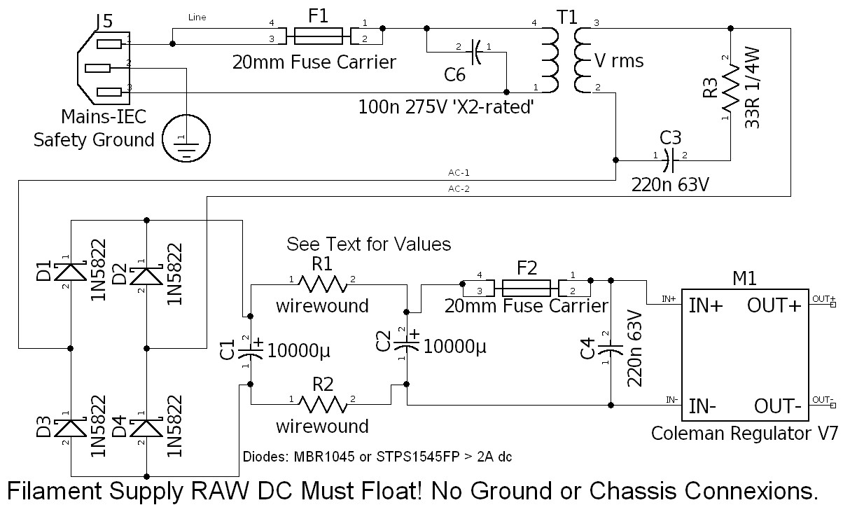
"Filament supply RAW DC must float! No ground or chassis connexions"
So trough the Rk, Io is going only. That 1A is going trough the filament only...
And this 35mA (from Yours 1.035A) is active with abs(-50V) so the dissipation at Rk is 1.75W
.
Please take a care it could be very dangerous!
...
Last edited:
Read this https://www.audioasylum.com/cgi/t.mpl?f=tubediy&m=181722.That is not true - filament DC bias is NOT connected to PS ground. So no current of 1A (in this case of 6C4C) from DC heat to ground!!!
12.5mA / div !!!Hi euro21 You are talking of 25mA but in the graph Io=12.5mA
Hey - thanks! That's a great link. I can see from the date that I've been using filament bias since 2010. That's 12 years already and many, many builds. For years I used PSE 4P1L outputs in filament bias and they were quite good, though not equal to a 2a3. Filament bias came from Thomas Mayer to us DIY guys, and it's good to read his comments. He has deleted most of his DIY stuff from his site, and thinks of himself as a manufacturer these days with his uber-elegant and expensive amps and preamps and his own range of tubes. Between Thomas and Rod Coleman we now have filament bias as the bias of choice for DHTs. Those 2 guys have really made a difference!
The raw power supply is floating and it goes to ground through the bias resistor. Hence ALL current of 1.035 A goes through such resistor. That is filament bias. Otherwise it would be called cathode bias. Clearly you have never done it.That is not true - filament DC bias is NOT connected to PS ground. So no current of 1A (in this case of 6C4C) from DC heat to ground!!!
The famous Iron-man has morphed to become the Thoriated-Tungsten-man.... thinks of himself as a manufacturer these days...
Ha Ha! Have you seen the amount of iron in his builds? He must be Lundahl's best customer. Have you seen his latest Facebook page with lots of pictures of his builds? Pure Bauhaus - architecture! Extraordinary.The famous Iron-man has morphed to become the Thoriated-Tungsten-man.
Yes he's Mr Elrog now. I wonder where the name came from.
Yes but it this case filament supply is not floating - as You wrote that warning in the manual...It's only the Raw DC (rectifiers, capacitors) that are floating.
Filament Bias: REGULATOR OUTPUT connects FIL-( NEG) to anode-supply-0V.
This makes I(Rk) = If + Ia
thanks for clarifing
Yes I saw now 50mA top value... Thanks12.5mA / div !!!
But this not change the wrong results of simulations with harmonic orders in that online soft.
Yes BUT - Only in this type of the connection of NON-Floating Filament supply.The raw power supply is floating and it goes to ground through the bias resistor. Hence ALL current of 1.035 A goes through such resistor. That is filament bias. Otherwise it would be called cathode bias. Clearly you have never done it.
You right about that, I didn't try that way, and I never will. Because of too high disipation and hard limit in the Anode voltage that is a must with this way. I tried only Floating regulated DC with CCS module. Own design...
This non-floating way limits the design even for lower filament currents, and for higher filament current of DH power tubes, is almost impossible to achieve safely because of high dissipation...
.
Still the rest of Your parts of the schematics are not good...
And there was no clear schematic of the filament-Cathode resistor circuit shown...
- Home
- Amplifiers
- Tubes / Valves
- DHT preamp, 2A3 preamp