Please - not true. Read the posts again. I reply the arguments which is not my but facts from the techical domain. Even wrote some formulas with explanation. Actually You gave just phrases. It is always the same story: wrong settings without basic understanding versus "carefully choosen types and brands" for the "best sounding performances". Simply it is not happening - THAT not sounding any good it is JUST working...Bear in mind that you are giving us nothing more here than a string of words - nothing more.
I dont want to talk in this manner without arguments and exclusively with other subjective and irrelevant things. I did not offend anyone. Just try to point what is wrong in the sch but also how can could be improved...
Yes I will post some sch with improved settings. But just to respect other members, might interested in same topic,as a normal conversation input and way.
How do You know that I didn't made anything with DHT?As far as I know - and judging from your comments - you've never in your life built a stage in filament bias with a large DHT like 10Y, 46 or 6C4C. Until you have, frankly you don't know what you are talking about.
Just opposite i did...
But does not matter much is the DHT or Indirect H, if the load, termination, coupling C have wrong almost random values.
.
I have strong feeling based on Your comments, with huge misunderstanding of basic terms and functions, that You actually didn't went trough available technical literature a lot...
"But does not matter much is the DHT or Indirect H..."
Of course it matters - read the title of the thread "DHT preamp, 2a3 preamp". Anyone can design something with indirectly heated tubes - you don't even have to design it, just buy a cheap Chinese PCB off ebay.
So now is the time to give us your actual schematic, Zoran. A 6C4C stage in filament bias. Until then all your comments are meaningless to me.
Unless your design actually works and can be built successfully this is all just hot air. My designs have all been built and they all work.
When I see your design I'll be very happy to make comments on your mathematics, your formulae and all the rest of it.
No design..... nothing to discuss.
Last edited:
Zoran,
Boy, I sure wish there was a THUMBS DOWN emoji...if there was, you'd have a BIGUN!
I'll be waiting for your design to appear, with your comments about whether you built it or not, and if you did build it, what it does for the music. I will not hold my breath waiting.
Robert
Boy, I sure wish there was a THUMBS DOWN emoji...if there was, you'd have a BIGUN!
I'll be waiting for your design to appear, with your comments about whether you built it or not, and if you did build it, what it does for the music. I will not hold my breath waiting.
Robert
There is no point to continuing the dialogue any more. You are offensive, hostile with provoking behaviour."But does not matter much is the DHT or Indirect H..."
Of course it matters - read the title of the thread "DHT preamp, 2a3 preamp". Anyone can design something with indirectly heated tubes - you don't even have to design it, just buy a cheap Chinese PCB off ebay.
So now is the time to give us your actual schematic, Zoran. A 6C4C stage in filament bias. Until then all your comments are meaningless to me.
Unless your design actually works and can be built successfully this is all just hot air. My designs have all been built and they all work.
When I see your design I'll be very happy to make comments on your mathematics, your formulae and all the rest of it.
No design..... nothing to discuss.
Please keep listening the DHT, or any other high voltage device, with 100V of anode voltage and low current.
With Coutput value, cutting out the bass. And advertising to the members how good it sounds. But offcours without, measurements
without anu calculations, without static graph, without simulations.
There is no need to wait for "My" design. It is not my or anybody else property. You can do it by your own. It is among us almost hundred years.Zoran,
Boy, I sure wish there was a THUMBS DOWN emoji...if there was, you'd have a BIGUN!
I'll be waiting for your design to appear, with your comments about whether you built it or not, and if you did build it, what it does for the music. I will not hold my breath waiting.
Robert

Just respect the tube datas and device function. Do not ignore the facts, tube are voltage device, respect the time constants for minimum phase shift etc... Hold the breath and start to read some official literature...
After You built an example please do some measurements to compare with simulation results just as some scientific approach...
Then talk about the subjective reception of sound quality.
.
I simply do not believe personal statements (always affirmative) from poor design without any argument measurements... Sorry.
cheers.
I have done it several times - I have built many 10Y, 46, 112A, 2P29L, 4P1L, 01A and 6C4C stages in filament bias. You clearly cannot give us a design for a 6C4C in filament bias because you are unable to do so. I ask you for a simple recipe for how to boil an egg and I get a lecture in thermodynamics. Where is the egg?There is no need to wait for "My" design. It is not my or anybody else property. You can do it by your own.
This site is called DIY Audio. DIY means "Do-it-yourself". It's for audio enthusiasts who build their own gear, like I do. It is not called "Lectures-on-the-theory-of-electronics Audio". If all you want to do is lecture posters on electronic theory you are on the wrong website.
Last edited:
You repeted this sentece more than 3 timesI have done it several times - I have built many 10Y, 46,
but Ypu must understand that it is NOT an valid argument. IF You done all of it like this one with extremlu underrated Anode voltage, wrong time constants and minor working current You just repeated the mistakes...Exactly, but NOT trough advertising wrong informations and non-techical, "approach". Again, with just empty words, for members in public domain to believe to.This site is called DIY Audio. DIY means "Do-it-yourself". It's for audio enthusiasts who build their own gear, like I do.
This is totally opposite to the goals and praxis of this forum.
Maybe You are in right this time?If all you want to do is lecture posters on electronic theory you are on the wrong website.
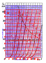
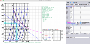
@Zoranthis is the static settings graph from schematic #94. Showing that the tube are out of the linear region, too small Anode voltage, and very small current.
It is customary for a design on multiple stages single ended topology to take advantage of cancellation of H2 distortion. The final H2 residual is also advantageous in reducing some of speaker driver H2 on single driver speaker system.
Zoran,
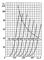
IMHO nothing wrong with this (100V, 25mA, about -16.5V, Ri: 967R) 6C4C operating point, if you use this tube with low (+/- 2..3V peek) grid swing (preamp).
BTW 25mA isn't "low current", large transmitting tubes as preamplifier also works in same region.
sample:
http://trioda.com/tools/triode.html
simulation

At 6k8 load, it produces about 0.36% THD, mainly h3.
At 200V, 60mA, -33V (Ri: 788R) the THD (at same swing, 6k8 load) is about same as previously, 0.36%, mainly h3.
IMHO nothing wrong with this (100V, 25mA, about -16.5V, Ri: 967R) 6C4C operating point, if you use this tube with low (+/- 2..3V peek) grid swing (preamp).
BTW 25mA isn't "low current", large transmitting tubes as preamplifier also works in same region.
sample:
http://trioda.com/tools/triode.html
simulation
At 6k8 load, it produces about 0.36% THD, mainly h3.
At 200V, 60mA, -33V (Ri: 788R) the THD (at same swing, 6k8 load) is about same as previously, 0.36%, mainly h3.
what do You mean of multiplying SE stages? one SE pramp stage + 2 x SE amp stage@Zoran
It is customary for a design on multiple stages single ended topology to take advantage of cancellation of H2 distortion. The final H2 residual is also advantageous in reducing some of speaker driver H2 on single driver speaker system.
or just 2 x SE serial preamp stages?
Hi euro21 You are talking of 25mA but in the graph Io=12.5mAZoran,
IMHO nothing wrong with this (100V, 25mA, about -16.5V, Ri: 967R) 6C4C operating point, if you use this tube with low (+/- 2..3V peek) grid swing (preamp).
BTW 25mA isn't "low current", large transmitting tubes as preamplifier also works in same region.
sample:
http://trioda.com/tools/triode.html
simulation
View attachment 1119814
At 6k8 load, it produces about 0.36% THD, mainly h3.
At 200V, 60mA, -33V (Ri: 788R) the THD (at same swing, 6k8 load) is about same as previously, 0.36%, mainly h3.
These online toola are very useful, but should be checked with off-line simulation software in the full circuit network.
In that picture might look that settings are in linear region but if Ypu take a look in real published Anode characteristic - that is not a linear region.
I get H3=0.03% at the same point, with other java soft, (not spice)...
Last edited:
I doubt, it is not supose to be happened, just because of each stage phase inversion?Does not matter. In SE topology, H2 of one stage will cancel some H2 of the next SE stage.
Simple example:
1st SE stage have slight unequal (Imax-Io), (Io-Imin) values. after amlifing the signal will be in opposite phase giong into the 2nd SE stage where the same process is going on so the output is not canceled but sort of slight added the harmonic distortion?
Please try to simulate this? Or measure maybe?
BTW
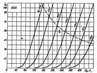
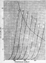
I compared 3 available graps of anode chrs for 6C4C thay are all the same.
.
I compared 3 available graps of anode chrs for 6C4C thay are all the same.
.
**** TEST Composite DHT *****************************************
* Created on 12/14/2022 09:41 using paint_kit.jar 3.1
* www.dmitrynizh.com/tubeparams_image.htm
* Plate Curves image file:
* Data source link:
*----------------------------------------------------------------------------------
.SUBCKT 6C4C_DHT 1 2 3 4 ; P G K1 K2
+ PARAMS: CCG=7.7P CGP=16.7P CCP=5.7P RFIL=6.3
+ MU=4.284 KG1=1455 KP=60 KVB=900 VCT=1 EX=1.372 RGI=2000
* Vp_MAX=500 Ip_MAX=100 Vg_step=10 Vg_start=-5 Vg_count=9
* Rp=10000 Vg_ac=2.5 P_max=15 Vg_qui=-22 Vp_qui=111
* X_MIN=66 Y_MIN=136 X_SIZE=520 Y_SIZE=515 FSZ_X=1419 FSZ_Y=777 XYGrid=true
* showLoadLine=y showIp=y isDHT=y isPP=n isAsymPP=n showDissipLimit=y
* showIg1=n gridLevel2=n isInputSnapped=n
* XYProjections=y harmonicPlot=y dissipPlot=y
*----------------------------------------------------------------------------------
RFIL_LEFT 3 31 {RFIL/4}
RFIL_RIGHT 4 41 {RFIL/4}
RFIL_MIDDLE1 31 34 {RFIL/4}
RFIL_MIDDLE2 34 41 {RFIL/4}
E11 32 0 VALUE={V(1,31)/KP*LOG(1+EXP(KP*(1/MU+V(2,31)/SQRT(KVB+V(1,31)*V(1,31)))))}
E12 42 0 VALUE={V(1,41)/KP*LOG(1+EXP(KP*(1/MU+V(2,41)/SQRT(KVB+V(1,41)*V(1,41)))))}
RE11 32 0 1G
RE12 42 0 1G
G11 1 31 VALUE={(PWR(V(32),EX)+PWRS(V(32),EX))/(2*KG1)}
G12 1 41 VALUE={(PWR(V(42),EX)+PWRS(V(42),EX))/(2*KG1)}
RCP1 1 34 1G
C1 2 34 {CCG} ; CATHODE-GRID
C2 2 1 {CGP} ; GRID=PLATE
C3 1 34 {CCP} ; CATHODE-PLATE
D3 5 3 DX ; FOR GRID CURRENT
D4 6 4 DX ; FOR GRID CURRENT
RG1 2 5 {2*RGI} ; FOR GRID CURRENT
RG2 2 6 {2*RGI} ; FOR GRID CURRENT
.MODEL DX D(IS=1N RS=1 CJO=10PF TT=1N)
.ENDS 6C4C_DHT
*$
Attachments
Last edited:
I thought you understand technical details of SE design, obviously not. Do the sim yourself, does not need to be tubes, H2 cancellation principle in multiple SE stages works for all active device including bipolars and fets.I doubt, it is not supose to be happened
Zoran - with your knowledge of electronics I am sure you could build a 2a3 stage with AC heating and cathode bypass capacitors. Perfectly simple, and you could just copy any 2a3 output stage and make the operating point whatever you like. Job done.
But what I have been trying to tell you in post after post is that designing a 6C4C or 6B4G stage in filament bias is quite different and requires different skills and a lot of complex modelling. It also requires compromises so that you don't end up with absurdly large cathode resistors, heatsinks and transformers for your "preferred" and "idealised" operating point. Fine for a 2a3 stage with AC heating. Useless for a 6C4C stage in filament bias. You just seem to refuse to understand this.
You have a good knowledge of electronics - why is it beyond you to work out what a practical design would actually look like? Sit down with a large piece of paper and a pencil and start sketching it out and then do the maths and calculate how big the actual parts are. Until you actually do this, you just don't understand what you have to do to build a working line stage in filament bias. It's a lot more complicated than you think it is.
Or alternatively, forget about filament bias completely and stick to a 2a3 with AC heating. And put an end to all this niggling about designs in filament bias which you don't have any knowledge of but which have been built by others and which work fine.
Last edited:
Thanks I will try to emulate this...I thought you understand technical details of SE design, obviously not. Do the sim yourself, does not need to be tubes, H2 cancellation principle in multiple SE stages works for all active device including bipolars and fets.
But that will imply to the multi SE stages can almost completly "cancel" H2... Maybe other Hs...
What kind of skills?requires different skills
Did You know that You can get 10X power from resistors by parallel 10 pieces 10 times value... And decrease eventual inductivity of the compsite resistor too?
Also spread out the heat to significantly larger area?
IF it is the power of disipation that huge problem...
please share with community?a lot of complex modelling
Yes indeed - I regularly parallel up cathode resistors in filament bias. That's how you do it. As I said, you also put these big cathode resistors outside the chassis because they get very hot.Did You know that You can get 10X power from resistors by parallel 10 pieces 10 times value... And decrease eventual inductivity of the compsite resistor too? Also spread out the heat to significantly larger area? IF it is the power of disipation that huge problem...
What kind of skills? Please share with community?
I have on several occasions explained how to construct a DHT stage in filament bias. Why - do you want to know how to do it? Start by looking at Rod Coleman's site Lyrima and study everything about his regulators and filament supplies. He supplies a lot of his regulators for those who build stages in filament bias. Buy a couple of his V9 regulators and try out a build with something simpler like a 2P29L. Look at Ale Moglia's site Bartola valves for plenty of designs. He uses active loads, I use resistor loads but the filament supplies are the same.
It is not possible that SE have dominant H2 not H3... this is not reliable online sim solution...At 200V, 60mA, -33V (Ri: 788R) the THD (at same swing, 6k8 load) is about same as previously, 0.36%, mainly h3.
Other soft showing H2 almost only, with H2=0.07% for 6Vp-p input
.
That is linear region, BUT Anode voltage still could be higher, and more important anode current is too high for using this tube in preamp. Anode power of 11.1W maybe, (because of higher current close to 60mA) is also unnecessary sufficient for this application...
Attachments
- Home
- Amplifiers
- Tubes / Valves
- DHT preamp, 2A3 preamp