first of all great thread
I have some questions about feedback, I see that most design have been based on the UCD.
it appears as the ouput signal is phase shiffted and proportioned then negatively summed with the input signal. is this correct?
Have any other methods of feedback produced as good result?
If I was to build a UCD using opamps instead of discrete what other circuitry is required
Hi,
That's because no other circuit makes as much sense.
It "can" be but that requires the use of an op amp. You can simply feed it to the inverting input of the comparator. Or you can sense the ground as well using differential feedback.
Leap frog feedback technique seems most promissing but isn't as straightforward.
Well you can't get around the use of a comparator so that's what you're replacing with an IC version. You'll at least require some form of level shifting on the outputs of that, which you'll see adds complication.
BTW I've recently discovered a minor problem with the single ended version of this circuit which I've been using for a few months now.
If I leave the power supply on for extended periods of time, I"ve noticed that probably due to pulses generated while rebooting my computer (which is the source) it must forward bias the input and allow some leakage through, possibly enough to partially bias the comparator output on. When this happens a loud snap can be heard when enabling the modulator.
It's happened twice now and the second time it blew a single transistor which was my cascoded output to the high side driver.
The only two times I've heard such a snap at turn on was after leaving the PSU on with the amp enabled for extended periods of time.
The immediate solution is obvious, dont' leave the PSU on for extended periods of time. Although a protection diode on the inputs may be worth a shot, if that's in fact what's causing it.
Regards,
Chris
I have some questions about feedback, I see that most design have been based on the UCD
That's because no other circuit makes as much sense.
it appears as the ouput signal is phase shiffted and proportioned then negatively summed with the input signal. is this correct?
It "can" be but that requires the use of an op amp. You can simply feed it to the inverting input of the comparator. Or you can sense the ground as well using differential feedback.
Have any other methods of feedback produced as good result?
Leap frog feedback technique seems most promissing but isn't as straightforward.
If I was to build a UCD using opamps instead of discrete what other circuitry is required
Well you can't get around the use of a comparator so that's what you're replacing with an IC version. You'll at least require some form of level shifting on the outputs of that, which you'll see adds complication.
BTW I've recently discovered a minor problem with the single ended version of this circuit which I've been using for a few months now.
If I leave the power supply on for extended periods of time, I"ve noticed that probably due to pulses generated while rebooting my computer (which is the source) it must forward bias the input and allow some leakage through, possibly enough to partially bias the comparator output on. When this happens a loud snap can be heard when enabling the modulator.
It's happened twice now and the second time it blew a single transistor which was my cascoded output to the high side driver.
The only two times I've heard such a snap at turn on was after leaving the PSU on with the amp enabled for extended periods of time.
The immediate solution is obvious, dont' leave the PSU on for extended periods of time. Although a protection diode on the inputs may be worth a shot, if that's in fact what's causing it.
Regards,
Chris
Since outputstages using a n-ch and a p-ch channel mosfet recieves a lot attention in this thread, I would like to present an alternative.
N-ch mosfets is known outperform P-ch mosfets by an order of a magnitude and are therefore a n-ch only outputstage is very appealing. I've had great success achieving this. Below you'll see two schematics that will work on a PCB. They differ only by the inputstage. One working as a voltage comperator and the other like a current comperator (similar to a current feedback opamp).
Propagation delay is about 200ns, the rise and fall times are arround 50ns and the deadtime also around 50ns.
By they way R44 can and should be replaced with a 20k+ resistor IRL, to lower the power dissipation in the resistor to realistic level. The 1k value is chosen to attain a fast startup time (50us) in simulations.
Some of the capasitors should also be icreased a lot IRL. 1nF for a current source is way to low. Again low values are chosen to attain fase startup and settle times.
N-ch mosfets is known outperform P-ch mosfets by an order of a magnitude and are therefore a n-ch only outputstage is very appealing. I've had great success achieving this. Below you'll see two schematics that will work on a PCB. They differ only by the inputstage. One working as a voltage comperator and the other like a current comperator (similar to a current feedback opamp).
Propagation delay is about 200ns, the rise and fall times are arround 50ns and the deadtime also around 50ns.
An externally hosted image should be here but it was not working when we last tested it.
An externally hosted image should be here but it was not working when we last tested it.
By they way R44 can and should be replaced with a 20k+ resistor IRL, to lower the power dissipation in the resistor to realistic level. The 1k value is chosen to attain a fast startup time (50us) in simulations.
Some of the capasitors should also be icreased a lot IRL. 1nF for a current source is way to low. Again low values are chosen to attain fase startup and settle times.
By they way R44 can and should be replaced with a 20k+ resistor
The supply voltage going into the MOSFET driver at Q57 should be lowered, I think, too.
There's no problem with Q57.
D35 limits the signal sving from -30V to -19V (11V difference). So the MOSFET gate voltage is well within it's limits (usually +/-20V with respect to source). You might argue about power dissepation then, but that's no problem either (even for a sot-23 package).
D35 limits the signal sving from -30V to -19V (11V difference). So the MOSFET gate voltage is well within it's limits (usually +/-20V with respect to source). You might argue about power dissepation then, but that's no problem either (even for a sot-23 package).
How to use the current comparator ? the two inputs seemes to be not synmmitric.
Build gate driver with discreet BJT, how could it be that fast? BJTs usually have storge time up to 1us and rise/fall time up to 100ns.
BTW:is 50ns a bit long for such high perfomance thing IRF6665?
Build gate driver with discreet BJT, how could it be that fast? BJTs usually have storge time up to 1us and rise/fall time up to 100ns.
BTW:is 50ns a bit long for such high perfomance thing IRF6665?
The current comperator works much like a normal comperator, when you think about how to make the feedback. Have a look at this paper:
http://www.national.com/an/OA/OA-30.pdf
One thing that differs CFB opamps from this current comperator is, that impedance of the non-inverting input is "0" and "infinity" for the inverting input. Usually it's the other way arround.
About the speed. General purpose BJT's are slow. However if you connect them in a way that secures the input BJT's from feedback through through their miller capacities, you've got speed. In other words, the voltage swing at the collectors should be low (the signal should be transfered with currents). Cascode is one way of doing this, but that's not enough. In the VFB comperator the input BJT's are connected to low impedeance emitters. The voltage swing here is low, but the amplification is still large. In an opamp a current mirror would have done the job, but this configuration is much better in a comperator.
The CFB comperator:
The input stage consist of a unity gain buffer. Therefore the inverting input has no problem with miller feedback, even with high impedance sources.
The non-inverting input however is the output of the unity gain buffer and is therefore very low impedance. The more current that goes into this "output" (we use it as an input), the faster the comperator is. You should connect a feedback network with an impedance of arround 50-100ohms, to ensure enough speed.
If you want to change with input is high impedance and witch is zero (switch the inverting and non-inverting input) you can do the following. Connect the collectors of Q62 and Q63 to the emitters of Q25 and Q16 insted of the bases. Also connect the 100pF capasitors to the bases insted of the emitters.
About the switching times:
These are not limited by the IRF6665 MOSFET's. It's the comperator stage and the high side driver that is the real bottleneck here. If you're really going to use the IRF6665 MOSFET's, then you actuall don't need the high current zetex BJT's in the output stage. BC8?6's and similar will do just as fine. Again, it's not the MOSFET equivalent gata capacities that sets the limit.
Hi,
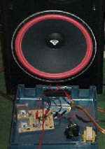
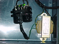
After all this time, I finally got some pics of my homebrew amp. The schematics are posted in this thread already, and would be most "similar" to the last one I posted here. Ideally no one will ask for a revised copy of it, but read this thread, learn, experiment, and make their own happen. This very thread contains all the information you need in order to do it.
Parts: Scanvenged scrap + a few samples.
Test & measurement equipment: DMM and ears.
Total cost: Alot of time!!
End Result: PRICELESS.
So thanks to all who've helped along the way!
To our hero's lost in battle:
-Two sacrificial 6' gettho-blaster speakers, that never sounded so good, for about 2 seconds.
-A dozen or so MOSFETs, their contribution and self sacrifice led to a better world for those who would follow them.
-Less then half a dozen BJTs, often overlooked on the battlefield, it couldn't have happened without them.
Regards,
Chris
Attachments

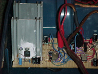
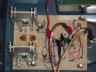
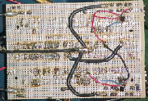
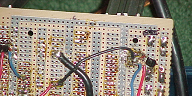
Last one.
Turn off transistor placed directly on the pins of the MOSFET.
The only part of this that even gets warm is the filter inductor. It's alot of fun, and sounds better than I ever hopped for (still listening to it six months later), so go for it, and good luck!
Turn off transistor placed directly on the pins of the MOSFET.
The only part of this that even gets warm is the filter inductor. It's alot of fun, and sounds better than I ever hopped for (still listening to it six months later), so go for it, and good luck!
Attachments

The most worryable things is the satuation/storage time of output transistor.
sovadk said:About the switching times:
These are not limited by the IRF6665 MOSFET's. It's the comperator stage and the high side driver that is the real bottleneck here. If you're really going to use the IRF6665 MOSFET's, then you actuall don't need the high current zetex BJT's in the output stage. BC8?6's and similar will do just as fine. Again, it's not the MOSFET equivalent gata capacities that sets the limit.
Why the current comparator have different structure on inv and non-inv input? Is there any differential input ones?
sovadk said:The current comperator works much like a normal comperator, when you think about how to make the feedback. Have a look at this paper:
http://www.national.com/an/OA/OA-30.pdf
One thing that differs CFB opamps from this current comperator is, that impedance of the non-inverting input is "0" and "infinity" for the inverting input. Usually it's the other way arround.
- Status
- This old topic is closed. If you want to reopen this topic, contact a moderator using the "Report Post" button.
- Home
- Amplifiers
- Class D
- Development of a "reference" class D starting point