Then all 46V regulators defecate the bedsheets. The low dropout ones, a bit less.
Of course, you could set the output voltage to be low enough to tolerate a 40V input. If your regulator has 1V (input - output) dropout, set it for 39V output. (Dial the pot). If your regulator has 8-10V (input - output) dropout, set it for 30V output. Remember that power dissipation in the regulator itself, is 20 amps times (input - output) voltage.
Of course, you could set the output voltage to be low enough to tolerate a 40V input. If your regulator has 1V (input - output) dropout, set it for 39V output. (Dial the pot). If your regulator has 8-10V (input - output) dropout, set it for 30V output. Remember that power dissipation in the regulator itself, is 20 amps times (input - output) voltage.
Last edited:
Then all 46V regulators defecate the bedsheets. The low dropout ones, a bit less.
Of course, you could set the output voltage to be low enough to tolerate a 40V input. If your regulator has 1V (input - output) dropout, set it for 39V output. (Dial the pot). If your regulator has 8-10V (input - output) dropout, set it for 30V output. Remember that power dissipation in the regulator itself, is 20 amps times (input - output) voltage.
This is my point, even low dropout regulators need an additional 15% overhead to regulate properly to account for AC mains fluctuations.
Really the best approach would be an unregulated cap multiplier using bipolars for those who can't deal with at least a 15% dropout (+ dropout of regulator).
Then "regulate" to (Vtrough - 1V). Remove all VREF circuitry and use those components to build a moderately precise Vtrough sensor. When mains is unsagged and Vinput_trough is 47V, you get 46VDC output. When mains is 15% sagged and Vinput_trough is 40V, you get 39VDC output. At no net increase in component count.
Best of all, you get negative feedback. If it's a good design you get giant amounts of negative feedback. This eliminates ripple far more effectively than a no-feedback capacitance multiplier, whose ultimate performance is limited by the Early effect.
Best of all, you get negative feedback. If it's a good design you get giant amounts of negative feedback. This eliminates ripple far more effectively than a no-feedback capacitance multiplier, whose ultimate performance is limited by the Early effect.
Best of all, you get negative feedback.
This is getting interesting.
I will try it
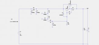
Ok here is a zero feedback unregulated Cap Multiplier design (low dropout) with 80dB PSRR at 100Hz.
Replace Darlington shown in circuit (Q5, Q4, R5, R7) with 2sd2083
https://www.semicon.sanken-ele.co.jp/sk_content/2sd2083_ds_en.pdf
If you want to use 4700uF caps then use 22 Ohms at R1, R3, R4
Replace Darlington shown in circuit (Q5, Q4, R5, R7) with 2sd2083
https://www.semicon.sanken-ele.co.jp/sk_content/2sd2083_ds_en.pdf
If you want to use 4700uF caps then use 22 Ohms at R1, R3, R4
Attachments
Last edited:
What use is this thread with all of the schematics removed??
Don't worry, circuits are being added, there is one on the other page as well.
Maybe I will do a pdf document later, with 3 or 4 options.
Full Dual Polarity Supply
R13, shows 10 Ohms, and R7 shows 100 Ohms, this is just to indicate anything between 10 Ohms and 100 Ohms will be ok, they should be the same value, just use whatever value you have laying around.
R1, shows 47 Ohms, R18 shows 100 Ohms, they should be the same value, just indicating anything between 47 Ohms and 100 Ohms will be ok
R19/R22 shows 4.7k and R11/R5 shows 2.2k, just indicating any value between 2.2k and 4.7k will be ok. They should be all the same, just use what you have between these values.
Refer back to this post for schematic.
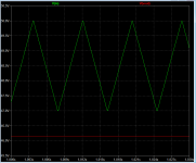
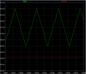
One circuit, two different input waveforms. Left picture no-sag, right picture yes-sag. Output drives 2.3 ohm resistor, i.e., 20 amperes.
In both cases, (Input - Output) is less than 1 volt. Darlington will have more than 1.4 volts (Input - Output), thus 40% greater power dissipation with 20 amperes flowing.
You can reduce this by changing to a FETlington but now you have to find a Pchannel JFET with Idss > 100mA to build your negative regulator. Yuck.
_
Attachments
Last edited:
In both cases, (Input - Output) is less than 1 volt. Darlington will have more than 1.4 volts (Input - Output), thus 40% greater power dissipation with 20 amperes flowing.
_
28W of intermittent dissipation (may not ever happen), no problem.
Around 2 to 4W constant dissipation depending on amp circuit.
The devices can either be mounted on the chassis of the amp or it's Class A heatsink.
Mark
I have a question.
Does the dotted line indicate the Darlington has a built in diode or just that I should add one myself?
Please refer to equivalent circuit diagram in datasheet (top right hand corner).
https://www.semicon.sanken-ele.co.jp/sk_content/2sd2083_ds_en.pdf
I have a question.
Does the dotted line indicate the Darlington has a built in diode or just that I should add one myself?
Please refer to equivalent circuit diagram in datasheet (top right hand corner).
https://www.semicon.sanken-ele.co.jp/sk_content/2sd2083_ds_en.pdf
Best of all, you get negative feedback. If it's a good design you get giant amounts of negative feedback. This eliminates ripple far more effectively than a no-feedback capacitance multiplier, whose ultimate performance is limited by the Early effect.
I have removed the voltage references from your circuit and only get 20dB PSRR at 100Hz.
It's possible you have made some other change I am not aware of.
If you could share the unregulated version that would be helpful.
Hi Mark on the unregulated version of your circuit, I am getting a drop out of 5.5V.
The Output Impedance is below 10 mOhms
PSRR at 100Hz is around 65dB or better but highly dependent on parts and setup.
The circuit is so sensitive to part selection and feedback values it would be a nightmare to setup.
Maybe you have found a way to avoid these issues.
I will try the original regulated version you posted.
With the regulated version setup for 5V dropout to allow for mains fluctuation
I get 65 db PSRR at 100Hz
Output impedance below 10mOhms
The performance is not as good as the circuit I posted earlier, but it is a lower dropout circuit and it is still very good.
So for people that want 5V dropout instead of 8V, this is definitely good.
I get 65 db PSRR at 100Hz
Output impedance below 10mOhms
The performance is not as good as the circuit I posted earlier, but it is a lower dropout circuit and it is still very good.
So for people that want 5V dropout instead of 8V, this is definitely good.
Last edited:
Hi Mark
Looks like the cap multiplier is better for the lowest dropout.
If you can get the unregulated version of your circuit working better than I can, that would be awesome. Better, as in 1V dropout unregulated.
The problem I am getting is that once you start adding some gain the voltage goes negative at the output.
It seems to work at 5.5V dropout but you may as well use the regulated version in that case.
I am sorry you are unable to get good performance out of an LDO with high gain and lots of feedback like the results in #329. But it appears you are perfectly content with the many-microfarads capacitance multiplier approach (schematic in post #325), so why not declare victory and move on. If you really, really need those last three volts, there's an easy solution: buy a different transformer. Same price, more volts, fewer amps.
I am sorry you are unable to get good performance out of an LDO with high gain and lots of feedback like the results in #329. But it appears you are perfectly content with the many-microfarads capacitance multiplier approach (schematic in post #325), so why not declare victory and move on. If you really, really need those last three volts, there's an easy solution: buy a different transformer. Same price, more volts, fewer amps.
Kind of sounds condescending and facetious.
I did get good performance just wasn’t able to get it to operate with 1V drop out. I used a sense resistor at the output to make it work (maybe this is the wrong approach).
If you don’t want to show your unregulated version with 1 V drop out, I will just assume it doesn’t work the way you claim.
I actually like your circuit, if it is possible to get it to work unregulated with 1v dropout, I would appreciate if you could show a working circuit.
Last edited:
Here's the LTSPICE input file, inside a .zip archive. I'll wait a few months before supplying the archive password, to give you plenty of time to design a few circuits of your own, and to experience the thrill of achieving your own victory. Without being polluted / distracted by someone else's ideas. This thread is after all named "Developing a Power Supply".
When I run LTSPICE on the circuit and then click "View ---> SPICE Error Log," the very first entries in the log are a list of the parts found in the circuit. Two capacitors (each 100uF), 6 diodes, 3 MOSFETs, 2 BJTs, etc:
_
When I run LTSPICE on the circuit and then click "View ---> SPICE Error Log," the very first entries in the log are a list of the parts found in the circuit. Two capacitors (each 100uF), 6 diodes, 3 MOSFETs, 2 BJTs, etc:
Code:
   --- Expanded Deck Component Count ---
C's 2
D's 6
M's 3
Q's 2
R's 8
V's 1
tot: 22Attachments
I will post the circuit I put together (the one that refuses to play ball with me) and hopefully you can point out what I should change, or where I did something completely stupid.
If I can get this Circuit to work with 1V dropout I will be incredibly happy.
I’m out now. When I get back home later today I will post.
If I can get this Circuit to work with 1V dropout I will be incredibly happy.
I’m out now. When I get back home later today I will post.
Last edited:
- Home
- Amplifiers
- Pass Labs
- Developing a Regulated Dual Rail Power Supply For FirstWatt Amps