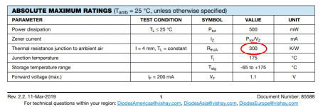
I think you will be able to gauge the safety or danger of that proposal, by looking at Figure 4 of this 500mW Zener datasheet. If your favorite Zener's datasheet doesn't have a graph like this one, then either switch to Vishay Zeners, or assume your Zener is perfectly identical to Vishay.
Also you can calculate the junction temperature, if you know (a) the temperature of the surrounding air, and (b) the power dissipated in the Zener diode, and (c) the thermal resistance of the diode + its package. Fortunately the datasheet tells you this (red circle).
_
Also you can calculate the junction temperature, if you know (a) the temperature of the surrounding air, and (b) the power dissipated in the Zener diode, and (c) the thermal resistance of the diode + its package. Fortunately the datasheet tells you this (red circle).
_
Attachments
At 100mW to 120mW looks like Junction would be around 30 degrees above ambient (rounding down of course) so junction temp would be around 60 degrees Celsius.
I tried adding additional bias in the manner you suggested, this did not improve the performance of the circuit further, so I will leave this mod out for now.
Since the sweet spot is around 12mA (60mW to 70mW), it looks like 0.5W Zeners will be adequate
I tried adding additional bias in the manner you suggested, this did not improve the performance of the circuit further, so I will leave this mod out for now.
Since the sweet spot is around 12mA (60mW to 70mW), it looks like 0.5W Zeners will be adequate
Since the sweet spot is around 12mA
With the change I made this no longer really applies.
I am getting good performance even below 10mA now.
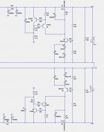
Full Dual Polarity Supply
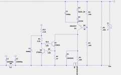
R13, shows 10 Ohms, and R7 shows 100 Ohms, this is just to indicate anything between 10 Ohms and 100 Ohms will be ok, they should be the same value, just use whatever value you have laying around.
R1, shows 47 Ohms, R18 shows 100 Ohms, they should be the same value, just indicating anything between 47 Ohms and 100 Ohms will be ok
R19/R22 shows 4.7k and R11/R5 shows 2.2k, just indicating any value between 2.2k and 4.7k will be ok. They should be all the same, just use what you have between these values.
Attachments
Last edited:
Latest power supply design
Many thanks for sharing your latest power supply design.
Your original design used BJT's and had a low dropout voltage - What is the dropout voltage on this design with FET's?
Also in the original design you had a large capacitor following the regulator - is this no longer recommended?
Many thanks for sharing your latest power supply design.
Your original design used BJT's and had a low dropout voltage - What is the dropout voltage on this design with FET's?
Also in the original design you had a large capacitor following the regulator - is this no longer recommended?
If you want regulated then 8 to 10V of headroom is advised.
If you just want a capacitance multiplier without regulation we can obviously have a much lower drop out, the performance won’t be as good but it will be better than just a regular CRC circuit.
I can go back and look at cap multiplier circuits if you like.
If you just want a capacitance multiplier without regulation we can obviously have a much lower drop out, the performance won’t be as good but it will be better than just a regular CRC circuit.
I can go back and look at cap multiplier circuits if you like.
Last edited:
The technology of "Low Dropout Regulators" is well developed; people routinely build excellent voltage regulators whose (Input - Output) drop is less than 1 volt. However, to make one which operates correctly requires analysis of feedback control systems, and if your analysis is wrong, your regulator will oscillate. Thus some hobbyists shy away from Low Dropout Regulators, figuring that the risk of oscillation is not worth the reward of low (Input - Output) drop.
There are loads of Low Dropout Regulator ICs, here is one whose (Input - Output) is very low: just 100 mV while delivering 2 amperes of load current
https://datasheets.maximintegrated.com/en/ds/MAX38904A-MAX38904D.pdf
The same ideas used inside ICs, can of course be used outside ICs: in discrete-component circuit design at the board level.
Unfortunately 2A of load current would not meet my requirements.
I wouldn't specify using a regulator that wasn't at least capable of twice the current the amp was rated for, so I would want a regulator capable of around 20A. I don't want the regulator being a bottle neck in anyway.
This is Pass diy, so I try to keep to the philosophy of making simple circuits the best they can be.
Last edited:
For fets it will be around 4V, for bipolars it will be less than 2V, eg 2Vbe depending on the design eg type of Darlington configuration etc.
For pure cap multiplier I would be inclined to use bipolars. It's matter of finding a bipolar that is capable of 20A that will also have decent bandwidth without feedback.
For pure cap multiplier I would be inclined to use bipolars. It's matter of finding a bipolar that is capable of 20A that will also have decent bandwidth without feedback.
Last edited:
Mark,
thanks for you input, I the (pretty distant) past I have replaced a LM317/337 on a dual regulator PCB for a DSP-board with some "fancy" LT parts and I had a weird noise, I would say very high pitch motorboating...
Since then I stay away from them, but your comment made me want to look into it again (if/when needed) and I know what to look at..
@pico , sorry for OT, doesn't happen often in the Pass forum")
Max
thanks for you input, I the (pretty distant) past I have replaced a LM317/337 on a dual regulator PCB for a DSP-board with some "fancy" LT parts and I had a weird noise, I would say very high pitch motorboating...
Since then I stay away from them, but your comment made me want to look into it again (if/when needed) and I know what to look at..
@pico , sorry for OT, doesn't happen often in the Pass forum
Max
Pico,
sorry, you know I don't know anything about circuits... but can't one use the regulating features of a particular IC and have a mosfet or whatever handle the high power/dissipation part ?
Cascoding is a word that makes tilt in my head, but is certainly not appropriate.
Max
sorry, you know I don't know anything about circuits... but can't one use the regulating features of a particular IC and have a mosfet or whatever handle the high power/dissipation part ?
Cascoding is a word that makes tilt in my head, but is certainly not appropriate.
Max
Maybe these
https://www.semicon.sanken-ele.co.jp/sk_content/2sb1383_ds_en.pdf
https://www.semicon.sanken-ele.co.jp/sk_content/2sd2083_ds_en.pdf
Regarding cap multiplier that is.
https://www.semicon.sanken-ele.co.jp/sk_content/2sb1383_ds_en.pdf
https://www.semicon.sanken-ele.co.jp/sk_content/2sd2083_ds_en.pdf
Regarding cap multiplier that is.
Last edited:
Pico,
sorry, you know I don't know anything about circuits... but can't one use the regulating features of a particular IC and have a mosfet or whatever handle the high power/dissipation part ?
Cascoding is a word that makes tilt in my head, but is certainly not appropriate.
Max
If you use an IC chip to control a mosfet you will still need 8 to 10V overhead for good regulation.
The circuit I proposed earlier kicks butt, made from very few parts.
A straight bipolar cap multiplier without regulation is probably the best compromise, if Low Drop Out is of highest priority.
There are other options but it's not in the spirit of Pass diy.
Last edited:
... I would want a regulator capable of around 20A. I don't want the regulator being a bottle neck in anyway...
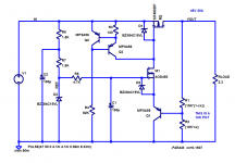
Here is a quick sketch of a 5 transistor voltage regulator which outputs +46V DC at 20 amperes. {Math check: 46V / 2.3 ohms = 20 amps. check!}
Don't assume the circuit is perfect, don't blindly drop it into a piece of audio equipment without redesigning it yourself and "owning" the redesign. In fact, I may or may not have intentionally left a few bugs, weaknesses, and flaws in the schematic, simply to encourage you to do your own design and to learn from the experience.
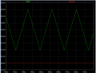
Notice that the dropout voltage (Input - Output) is 1.0 volt. The input voltage falls as low as 47.0 volts and yet the output voltage is a stable 46.0 volts DC.
It regulates pretty well too. Output ripple is noticeably less than input ripple.
_
Attachments
Here is a quick sketch of a 5 transistor voltage regulator which outputs +46V DC at 20 amperes. {Math check: 46V / 2.3 ohms = 20 amps. check!}
Don't assume the circuit is perfect, don't blindly drop it into a piece of audio equipment without redesigning it yourself and "owning" the redesign. In fact, I may or may not have intentionally left a few bugs, weaknesses, and flaws in the schematic, simply to encourage you to do your own design and to learn from the experience.
Notice that the dropout voltage (Input - Output) is 1.0 volt. The input voltage falls as low as 47.0 volts and yet the output voltage is a stable 46.0 volts DC.
It regulates pretty well too. Output ripple is noticeably less than input ripple.
_
What happens if mains voltage sags by 15% and you end up with 40V at the input?
I like that you kept the design simple. Nice one.
I will check it out.
What is output impedance?
What is PSRR?
If you want me to determine these things, I will.
Last edited:
- Home
- Amplifiers
- Pass Labs
- Developing a Regulated Dual Rail Power Supply For FirstWatt Amps