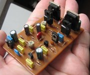
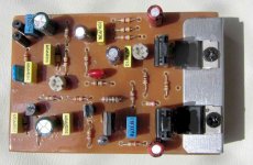
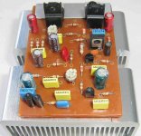
You are watching just a model...a non working thing..made to show
how the amplifier will look.... to evaluate its size...also details alike transistor mounting....those things.
The parts you may observe zooming in are not the real values..this is a non working circuit...a board with coloured parts over...respecting some positions of transistors and resistances only..something to show...a Maquette...a model only.
regards,
Carlos
Attachments
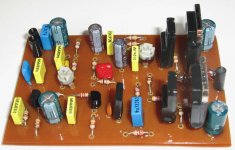
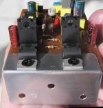
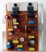
Capacitor values crazy there..the drivers show are burned 7805 regulators....this is
fake construction...a fause circuit that do not works...if powered will explode...made to show you only.
Please, those boering guys, do not came to tell me that resistances have wrong value...aaaagh!
regards,
Carlos
fake construction...a fause circuit that do not works...if powered will explode...made to show you only.
Please, those boering guys, do not came to tell me that resistances have wrong value...aaaagh!
regards,
Carlos
Attachments
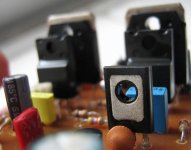
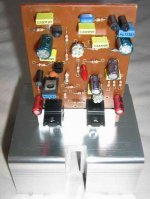
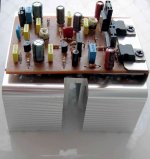
Hey comentators, simulators, re-designers, and others...try
to construct something to show us too...not only talking and calculating...audio is much more than that.
In other words...take care of your own ears...produce something good to your ears.
regards,
Carlos
to construct something to show us too...not only talking and calculating...audio is much more than that.
In other words...take care of your own ears...produce something good to your ears.
regards,
Carlos
Attachments
Carlos - i know that this question related capacitors C16 and C19 was discussed... and i don't ask that nobody is customizing the boards to my needs....")
if i need the boards to look in some other way you know that i know how to make them suitable for me - what i am trying to tell you is that those caps can be made in front of the transistors and you can leave to everybodies choice to use them or not - avoiding the questions if somebody would like to use those caps and still bend the trensistors to L shape heatsink .... with the board that was kindly provided by Greg you can only install output transistor fromthe bottom of the board if you want to use C16 and C19....
maybe someone will have heatsinks that will not be that way and would like to bend transistors over the pcb - from the top - and could not do it or to leave out the capacitors and do it...
you know...
i hope that i am more clear now....
otherwise - the pcb is very clear and nice looking....
Re: You can do...all of you, whatever you want..including modifications
LineX-PA1
lineup x power amp v1.0
thanks, Carlos
I like this idea!
... maybe a new classic amplifier
In the year of 2037
some young DIY builder will start new topic:
LineX-PA1 - cap replacement & modifications ??
Regards, lineup
.. in fact has got a new power amplifier
( JFET input, BJT VAS and HEX MOSFET output )
under design .. very promising test data!!
destroyer X said:
..alike i have suggested to Mr. Lineup.... make your own version
-----
The name can be, in Lineup case...
LineX amplifier
-----
also you can do that Sparkle...i would be happy..at least having dozen amplifiers, around the same thopologie, the chance to have more guys listening and evaluating will be bigger...may result good.
regards, Carlos
LineX-PA1
lineup x power amp v1.0
thanks, Carlos
I like this idea!
... maybe a new classic amplifier
In the year of 2037
some young DIY builder will start new topic:
LineX-PA1 - cap replacement & modifications ??
Regards, lineup
.. in fact has got a new power amplifier
( JFET input, BJT VAS and HEX MOSFET output )
under design .. very promising test data!!
Hugh has made a wonderfull job Sparkle...so good that it is a hell to scape
from his good idea.
In my view...the same view you have...constructing alike Hugh did,
in his 55, will be the best idea.
I tried to avoid...as people can create their own ideas too..related to transistor coupling to heatsink..mount over heatsink...and maybe they may be able to create even better ideas than Hugh did...even telling you frankly that i have some doubts about it.... that folk...well Hugh..the one is really great!
Those condensers, placed into the rails power input lines, did not sounded here at my home... the remotion of them, will not be a problem if wiring from supply, to the board ,was made short..also if supply is good enougth.
I use, at least a 104 capacitor in that position...because those miliohms we can face, from the wiring resistance, may create a annoying "time constant"...so...the capacitor will take care of that, also will send to ground interferences that may enter from the supply...also will send oscilations to ground..supply variations of voltage resultant of HF modulations there.
Mine supply, for sure will not let interferences goes into the amplifier...It is a CarlosFM idea..very good one...but people can produce other supplies, with less care, related to avoid interferences from mains.
Yes guys!...i have installed them..those electrolitic condensers... very near the output.... into output colectors to ground.. rails to ground..and really near the transistors...but did not sounded!
So... if people decide to remove those condensers, and to install a L shape aluminium there....of course will be very pretty...and this can be fixed to non L shaped heatsinks too.
I would like to see people free to create......but not free to make modifications in the schematic shown...
The reason why is that i cannot control the hundreds of possibilities that can be made, this single schematic can hold hundreds of variations...and many of them will create a very different amplifiers.
This will need tests Sparkle, as you know..as you are an engineer.. the unit will need to be constructed, and this will be needed to guarantee that the amplifier is fine..and as i have opened the thread...i am responsable for the thread...if the one that created ideas was lazy..i will turn crazy doing all the job for him.
If those options, modified amplifiers were posted in this thread, as i am the responsable...i will have to explain those details, to test, to construct and to guarantee...and the real thing is not mine!!!...so...it is better that people, if they want to make modifications, that they open their own thread, with another amplifier name, they can mention Dx or not...their will to do this or not to do, and goes to defend their ideas, to answer the questions that will appear, of course, they will have to make schematic...board, copper lines layout and all hard work to show something "usefull" to our communitty.
This thread was created because the first one,full throotle, was crowdy... enormous quantity of things there....also this one i could not keept clean enougth of multiple schematics i have created because continuous listening and experiences made, so, there are many values and ideas....already confused enougth some guys.
I have a local friend...a Portuguese speaking friend ,that is already so confused that he is not following the thread anymore..ahahahahah!...sorry for that...he is saying that i am complicating to own some money constructing for him...ahahahaha....kidding of course..this is not honest to make.
Lineup has a pretty good idea..with lower power...but the problem is that he do not construct normally..he prefer simulations and to instruct young people about basic electronics and to discuss advanced electronics too...this way... i will not be happy to see his schematic published here....because i will turn crazy to make it, test it, and all those things...and this thread will turn even more confused.
Reason why i have invited him to open his thread, about his amplifier, that for sure will be a very good one.
regards,
Carlos
i understand - no problem...
but at least remove those caps from the pictures - not to confuse people .. well the idea is not form Hugh - it is a normal way of thinking... those caps (if you install them and try to bend transistors) are on your way.... right
i am kidding right - and trying to help...
i don't have time to do your amp right now - that is the problem ....will have time in near future as my attention is devoted here and to my other amplifier that is work in progress right now...
so, i am jumping like a popcorn here trying to help instead to make it - and for that i don't have time right now.....crazy world - we should all have 48 hours day... maybe we will...well, we could not finish everything after all.....
but at least remove those caps from the pictures - not to confuse people ..
well the idea is not form Hugh - it is a normal way of thinking... those caps (if you install them and try to bend transistors) are on your way.... right i am kidding right - and trying to help...
i don't have time to do your amp right now - that is the problem ....will have time in near future as my attention is devoted here and to my other amplifier that is work in progress right now...
so, i am jumping like a popcorn here trying to help instead to make it - and for that i don't have time right now.....crazy world - we should all have 48 hours day... maybe we will...well, we could not finish everything after all.....
Re: You are helping..posting things...as this makes the thread alive.
You are welcome Carlos
I am just glad that your interesting threads are read by people.
If you have something useful to contribute in 'my topics'
I wouldnt be too sad, to see you posting some ideas.
But some are so busy with their own stuff
they are totally focused onto this.
Some are good listeners (ears) .. other are good speakers(mouth)
and many can do both in a balanced way.
Some are rude and bad ... other are nice like little lambs (sheep child)
and many can be a little of both .. depending on situation.
lineup - have ears + mouth .... can be tough and nice .... to whom it may fit
destroyer X said:You are helping..posting things...as this makes the thread alive.
having always something posted to people read.
Already helping me a lot.
regards, Carlos
You are welcome Carlos
I am just glad that your interesting threads are read by people.
If you have something useful to contribute in 'my topics'
I wouldnt be too sad, to see you posting some ideas.
But some are so busy with their own stuff
they are totally focused onto this.
Some are good listeners (ears) .. other are good speakers(mouth)
and many can do both in a balanced way.
Some are rude and bad ... other are nice like little lambs (sheep child)
and many can be a little of both .. depending on situation.
lineup - have ears + mouth .... can be tough and nice .... to whom it may fit
Attachments
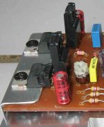
Thanks Lineup by you philosophic posts..very apreciated.
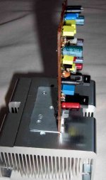
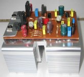
Here is one image, about the option to remove the rail condenser and to put it in another place...you may see the red ones at board sides.
Also the removal of the output coil..you may see it in the middle of the board.
Power transistors goes mounted over an L shape aluminium..screws gonna fix them in place...the longer L shape side will be screwed into some heatsink having large ammounts of thermic grease.
Of course you are watching small transistors...just to show in a model...also the rail filter condensers are fake... everything is fake in the image...but the shape, how it will look can be seen or imagined.
No insulator were use to this model...just some idea beeing shown....more hundreds ideas may exist...at your will.
The board will need some more milimeters long to hold the bigger transistors normally used.
This heatsink size can be enougth to one channel if a fan blower is used..this is able to dissipate 150 watts continuous if fan goes strong on it.
regards,
Carlos
Attachments
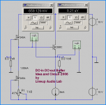
If you decide to use dual voltage supply...the one
having two outputs..one with 38 plus and 38 minus and ground
And another one with 35 plus and 35 minus and ground
Of course, as you know, those grounds are joined together.
In this case, the better is to remove the rail resistors...R15 and R18...but, if you decide to keep them there...please, increase the value to 180 ohms each one of them
Also you can avoid the dual output supply use...and you may keep the 82 ohms to the rails and will feed only 35 volts positive and 35 volts negative to the amplifier...in this last sittuation, the higher voltage to input will be not used.
But if you do nothing... assemble the way it is shown that will work fine either.
regards,
Carlos
Attachments
wow, are you using dual supply.....35vdc and 38vdc ??
Would it be possible to cut between TIP41 and output transistor, so that TIP41 is fed with the higher voltage
I have two supplies - a small with 58Vdc and a big with 52Vdc
Wonder if input and driver stage can used with 58Vdc
Nah, looks close - but I guess I could just use another driver fore the MJL/21193/21194 I have already
Could that be done without changes
- Status
- Not open for further replies.
- Home
- Amplifiers
- Solid State
- Destroyer x Amplifier...Dx amp...my amplifier