
LOL Nordic...this is fine..good mood.
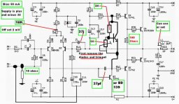
I will attach an image showing the VBE voltages and also voltages referenced by ground level.
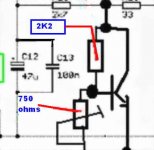
The blue voltages were measured with ground reference.
The Red voltages are VBE...volts from base to emitter.
There are small differences from the real circuit compared to
simulator voltages..i am providing you the simulated voltages.
Real voltages are different..but very small differences..around 30 milivolts or something....maybe multimeter errors.
Soon i will provide another schematic with current indications.
regards,
Carlos
I will attach an image showing the VBE voltages and also voltages referenced by ground level.
The blue voltages were measured with ground reference.
The Red voltages are VBE...volts from base to emitter.
There are small differences from the real circuit compared to
simulator voltages..i am providing you the simulated voltages.
Real voltages are different..but very small differences..around 30 milivolts or something....maybe multimeter errors.
Soon i will provide another schematic with current indications.
regards,
Carlos
Attachments
Hi x,
have you tried asking the simulator what happens to voltages and currents when the PSU supplies +-37Vdc?
Then what it reports when the loaded rails fall to +-30Vdc?
I am particularly interested in output offset, VAS current, driver currents (Ic & Ie) and output bias current.
have you tried asking the simulator what happens to voltages and currents when the PSU supplies +-37Vdc?
Then what it reports when the loaded rails fall to +-30Vdc?
I am particularly interested in output offset, VAS current, driver currents (Ic & Ie) and output bias current.
Thank you Andrew T...now i think it is fine.
Also i want to correct an error in my informations about the VBE multiplier made to Nordic.
The current that will cross the VBE multiplier transistor, the same current that will feed the VAS is around 7 miliamps.
I made the confusion, as the driver current is 10 miliamperes.
Sorry..big fat Charlie is turning a little old with 56 years old..and i use to make errors.
Sorry for that folks.
Soon i will provide you....today i will do it...informations about the whole circuit current.
regards,
Carlos
Attachments
As you know Andrew..when the supply voltage is reduced, the bias will be reduced
into the amplifier.... current will be reduced....and off set will remain almost the same, because it is controled by the differential, and this one has a voltage regulator there.
Well..you know those things Andrew.... i think since your 5 years old you have already dominated those things...as i have learned with i had 9 years old.
Constructing amplifiers we will face those realities daily,,,you may have forget as not constructing now a days..only teaching electronics..hehe
regards,
Carlos
Attachments

Re: As you know Andrew..when the supply voltage is reduced, the bias will be reduced
are you sure? Have you measured what happens in the simulator or in the as built circuit when the supply voltage is modulated?destroyer X said:
into the amplifier.... current will be reduced....and off set will remain almost the same, because it is controled by the differential, and this one has a voltage regulator there.
hehe...evaluating things by your questions we may have a lot of drunk electrons
flowing into that mess.
Well...as this worries you too much..use the voltage stabilizer i have suggested in this thread or other you prefere..this way those problems will not create concerns to you.
I am happy with the amplifier sounding fine...electrons can be free to make the mess they want.
ahahahhaa
Carlos
Well...saturday...i am still sleeping..using my pijama
pijama is the sleeping dressing we use in hot environment...silk shorts and small upper dressing.
Temperature 25 degrées celsius and winds from the west into the east, wind speed 12 Km/hour and ligth grey cloudy skies.
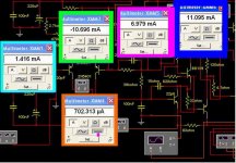
I have colected some information about current in the simulator (lazy i am)
In Orange colour you can see the first transistor, the first amplifier colector current.
In Blue colour you see the long tail current..both differential transistor current is travelling there..so..it is almost twice each leg current.
In green, the current is going to bias the zener and to feed the differential.
In Pink colour... shocking rose, you can see the current is travelling into the bias circuit (VBE multiplier, diodes or resistances) into the Voltage amplifier colector to emitter junction....this current travells from rail to rail..and resistances will be fixing the needed voltages during this travell.
In deep Ocean blue, you can see the current that is traveling into the differential colector to emitter junction.... this one show is when we use the old 120 ohms emitter resistance.... that one was replaced by a 180 ohms to reduce this current..to avoid drivers to be too much hot....now a days, current is a little bit less than 7 miliamps.
Well, the output is up to your decision.... 10 to 20 miliamps will be fine.
Those informations are not precise enougth.... each amplifier i have constructed had measured different voltages..because of parts, parts gain and biasing points...but may be helpfull to you..in special if you have the need to debug the circuit facing some failure or construction error.
Be happy...enjoy Dx sonics.
regards,
Carlos
pijama is the sleeping dressing we use in hot environment...silk shorts and small upper dressing.
Temperature 25 degrées celsius and winds from the west into the east, wind speed 12 Km/hour and ligth grey cloudy skies.
I have colected some information about current in the simulator (lazy i am)
In Orange colour you can see the first transistor, the first amplifier colector current.
In Blue colour you see the long tail current..both differential transistor current is travelling there..so..it is almost twice each leg current.
In green, the current is going to bias the zener and to feed the differential.
In Pink colour... shocking rose, you can see the current is travelling into the bias circuit (VBE multiplier, diodes or resistances) into the Voltage amplifier colector to emitter junction....this current travells from rail to rail..and resistances will be fixing the needed voltages during this travell.
In deep Ocean blue, you can see the current that is traveling into the differential colector to emitter junction.... this one show is when we use the old 120 ohms emitter resistance.... that one was replaced by a 180 ohms to reduce this current..to avoid drivers to be too much hot....now a days, current is a little bit less than 7 miliamps.
Well, the output is up to your decision.... 10 to 20 miliamps will be fine.
Those informations are not precise enougth.... each amplifier i have constructed had measured different voltages..because of parts, parts gain and biasing points...but may be helpfull to you..in special if you have the need to debug the circuit facing some failure or construction error.
Be happy...enjoy Dx sonics.
regards,
Carlos
Attachments
Hi Carlos,
It takes several days for me to read the whole thread just to learn some knowledge from you and to other brilliant designers. Everyday my interest on your design is keeping bigger and it boost up when I knew that you are working with SONY before coz I am a loyal admirer of sony products.
Now I decided to build your DX Amp and planning to incorporate this with a bass and trebble control circuit. And my question is, is there any restriction of your DX Amp when it incorporated to a bass and trebble control? if there is, what are this? Or do you have bass and trebble circuit design suited for this amp? I am so thankful if you will provide me. Because I am an audio fanatic who loves to adjust the level of the bass, trebble and even the midrange depending on the type of music I want to hear and sometimes my mode.
I want to build your amplifier so I could learn from this and understand the basic calculation in amplifier design which I am dreaming of..
Keep it up Carlos... and the whole team....you are all brilliant
Regards,
Nhix
Negative Bernhix, not brilliant....i am a little stupid
Observe dear Bern, that i have passed more than 40 years constructing other guy's schematics...and many of them exploded in my face and i have continued..doing and doing and doing.
The problems were errors..typing errors, magazine publishing errors..and sometimes untested circuits too.
I have delayed too much to try to understand how electrons flows..and now a days there are things that i do not understand completelly.
I am crazy enougth to try my own and i did it...when my calculations failed i made a try and error to find solution...when no try and error worked i found another diagram and i have copied the solution till i have learned some about.
I do turn very confused now a days..when i simulate things and real life appear enormous differences.... even knowing that parts are different...i do turn confused.
But thanks.... i think i deserve your words because i use to help younger folks...or the ones have even lower knowledge than i have..trying to translate in simple words (my small english and knowledge) something i have discovered when smoke have dissipated.... i have learned destroying many transistors...and i use to be sad when i remember those 2SC2922 burned because this idiot here, your friend, have injected too much volts into the base.
I will search something to install in the input...a passive tone adjustment control that may work... also will turn a lot of people scandalized because passive..hehe
Those other ones,using down the seventies and early eigthies, installed into the feedback line, are quality destroyers...better not to use them and face some impedance mismatch and perfectionist criticisms.
I have enormous support from Brilliant people...the shine is not mine...hidden and silent there are giants that use to write me with some advises..i will tell you they are the best ones i could find and the ones accepted my crazy character.
You could see clearly Doctor Bittner the genius, he studied by himself the theorics and practice, The best sonic designer Hugh Dean, the best researcher, the scientist from the first cicle distortion, Mr. Graham Maynard and some important folks that do not want to appear...they are helping me and saying..Go Carlos..go!
You have made my day..turned me more happy...you gave an injection into my Ego...i was needing something alike that...thank you.
Carlos
I cant get the voltage over the 10R resistors lower than 1.7v almost at 0 on pot... you said not to go all the way to 0R
Nothing seems to get hot... the 10R resistors are lukewarm, but heatsink still styaing cold after few minutes...
output offset seems unstable somewere between 1 and 3mv ... not sure my multimeter is so accrate at this range...
What next? !!!
DC supply is 33V
Waited few minutes, tried again, voltage starts at about 1.35v then creeps upward slowly, while DC offset goes down slowly from 14mv to 3mv, not smelling smoke...
Re: Deeply honored with your presence Mr. Rabittz
Thanks for your kind words Carlos (I'm blushing) and yes I will sit in my chair and enjoy the show.
Keep it up as this thread is so valuable to amp builders.
Cheers
Peter
destroyer X said:
Push a chair please...or sit on the sofa and stay with us..this will make us more rich with your presence.
Carlos
Thanks for your kind words Carlos (I'm blushing) and yes I will sit in my chair and enjoy the show.
Keep it up as this thread is so valuable to amp builders.
Cheers
Peter
Attachments
Are you using VBE multiplier or resistances Nordic.
Using resistances you can go to the zero ohms position to reduce a little your bias.
In the VBE multiplier you may try the other direction to obtain bias reduction....
The heatsink will provide you that fake result...it may delay minutes to reach the correct surface temperature...as in idle, in stand by mode, you will be dissipating small heat.
170 miliamperes, or 0.170A...yeah..you can write 0.17A multiplied by the voltage you have in your rail will result in half rail heat in stand by mode:
0.17 multiplied by 33 = 5.61 Watts to each rail.
So....both rails will be two times 5.61 Watts.....11.22 Watts.
Of course you can keep the things the way they are...but...biasing with lower voltage...just forcing transistor into conduction will produce better details...very small signals that will be lost when you go further into the bias....i also feel that strange..but happens in practice...day by day testings shows me that.
This is the reason that Hugh asked 54 milivolts to his Aksa 55.....he do not acept 56 or 52 miliamps....also he is now a days constructing his amplifiers...not more beeing sold as Kits...this way he controls that bias with care...people constructing may adjust the amplifier a little bit out of the optimized bias point.
Dx amplifier gives the best when adjusted to 50 miliamps to the negative rail and 60 miliamps to the positive rail.....and can work fine till 120 miliamps.....increasing...some losses in very low level details....decreasing under 30 miliamps to negative rail it starts to distort in very low levels.
Ahahahhaha...increasing too much..going to class A...you will loose power and will burn your fingers and transistors for the long run....audio will turn compressed and a little mufled..dinamics will be smaller and bass punch will turn precise, perfect and awfull too.(subjective, personal opinion).
I will be more happy with this bias sligtly smaller dear Nordic...1,35 volts over 10 ohms is 135 miliamps..... a little over the limit in my idea...but may work fine...difference is in a very little volume.... listening a 100 milivolts level...i do not believe you are boring alike i am using headphones...so.... will be good.
Well...your amplifier is working fine..if you biased and had low off set you suceeded.... now check all your VBE voltages...them may be from 500 to 630 milivolts.... the prefered situation is 590 milivolts.
Power is current (in amperes) multiplied by voltage (expressed in volts)
0.135A multiplied by rail voltage of 33 = 4.45 Watts.... double because you have two rails...so.... will result in less than 9 watts.
It is reasonable...despite i prefer 3.5 watts... 35 volts supply and 50 miliamps each rail..... well..sligtly more, as the positive rail has bigger current because of the zener biasing current...and this one have to be 10 times the needed stabilized current you will need for the long tail.
I know you are around Peter..also Sea to Sea.
regards,
Carlos
When I started amp with 666R on trimpot, it gave 1.4A over the 10R resistors, turning one way voltage goes up, turning other voltage goes down, but lowest voltage is over 1V as posted before... do you think swapping the 2k2 resistor on VBE for 2k will help or make it worse? (mine is allready 2k2 by mistake... it was the last thing I did...)
At least it made no flames so I can build other channel in peace... and compare the two... will show up any human errors..
At least it made no flames so I can build other channel in peace... and compare the two... will show up any human errors..
- Status
- Not open for further replies.
- Home
- Amplifiers
- Solid State
- Destroyer x Amplifier...Dx amp...my amplifier