Jopseph Siejack says i am a "dirty old man"....he is right and precise.
Carlos
There is no point in getting old without being dirty.
Advertisement of Dx Class made to Brazil
It says:
"that hot day and an almost frozzen Coca Cola.... the pleasure to listen a Dx Class"
https://www.youtube.com/watch?v=rjQzW7fDGJY&feature=youtu.be
A young brazilian made it to me... a redneck.... very creative...i love that spirit and also i am a Coca Cola addict.
regards,
Carlos
It says:
"that hot day and an almost frozzen Coca Cola.... the pleasure to listen a Dx Class"
https://www.youtube.com/watch?v=rjQzW7fDGJY&feature=youtu.be
A young brazilian made it to me... a redneck.... very creative...i love that spirit and also i am a Coca Cola addict.
regards,
Carlos
Hi everybody, my name is Michele and i write from Italy.
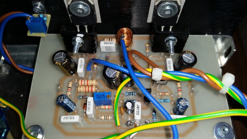
I write for an opinion from you, builders of the dx amp. I builded it, with pcb from gregs site.
It worked for a short time and sounded perfectly. i could regulate the bias and the dc offset, but the 2sa1943 blew many times.
No overcurrent because I monitored it constantly. I substituted about 5-6 transistor but after few minutes they always blow with fire and flames. I also burn a seas woofer.
Don't know what to do. Transistors are from mouser and seem genuine. Supply is 34-0-34 vdc.
Any help will be appreciated.
Regards
Michele
Hello everybody,
my name is Michele and I write from Italy.
I write for an issue with dx amp...I build it, using pcb's from Greg's site and initially it seemed work perfectly. After I made the first bias and dc offset regulations I played some music, but after few minutes the FIRST 2sa1943 blewwith fire and flames....get out also a SEAS woofer
So, very sad and angry, I tried to substitute the faulty device, but after few minutes it blew again and again and again for about 6-7 times...No overcurrent through the transistors when it bler because I constantly monitored it with DMM...the bias was always nice (about 80-90mA) and also the dc offset (near 0-5mV)...
Toshiba devices are from mouser and seem genuine....power supply is 24-0-24VAC (cca. 33VDC).
heatsink are very large, I use mica pads + thermal grease for screwing the transistors on it.
Now I don't know what to do, the amp has sounded very good to me, never heard a bass like that...
What could be the problem???
any help will be appreciated, and sorry for the bad english...
regards
You need to use 10R power resistors (safety resistors as recommended by Carlos) in series with rail supplies (monitor voltage across it) until setup and setup. It will prevent smoke and flames and give you indication of virtual short which is what it take to fry one if of those transistors. A fake sa1943 will burn like that too but since Mouser probably ok. I would remove the output transistors and debug circuit to make sure base voltage from TIP drivers is not hitting the rail. My guess is one of the small signal transistors is fried and fully conducting hence telling the drivers to hit the rail. Also don't use expensive speakers to test until you know it's good.
My guess is that you have either a short from the thermal tab to the heatsink (check for conductivity). Or a cold solder joint in your signal chain or a bad signal transistor. No point in replacing OPS until you have base voltage under control. Good luck.
My guess is that you have either a short from the thermal tab to the heatsink (check for conductivity). Or a cold solder joint in your signal chain or a bad signal transistor. No point in replacing OPS until you have base voltage under control. Good luck.
You need to use 10R power resistors (safety resistors as recommended by Carlos) in series with rail supplies (monitor voltage across it) until setup and setup. It will prevent smoke and flames and give you indication of virtual short which is what it take to fry one if of those transistors. A fake sa1943 will burn like that too but since Mouser probably ok. I would remove the output transistors and debug circuit to make sure base voltage from TIP drivers is not hitting the rail. My guess is one of the small signal transistors is fried and fully conducting hence telling the drivers to hit the rail. Also don't use expensive speakers to test until you know it's good.
My guess is that you have either a short from the thermal tab to the heatsink (check for conductivity). Or a cold solder joint in your signal chain or a bad signal transistor. No point in replacing OPS until you have base voltage under control. Good luck.
hi, I used 10R resisitor during setup and all was fine. you're right. But after recommended regulations have been done, current and supply were perfectly regulated, the transistor blew many times...also the same transistor...
I checked the circuit and it's ok, the pcb is taken from greg website, and simply printed as it is.... also the small transistor have been changed and the TIP too, but they were ok...so I'm thinking to an oscillation because the bias is not stable, but it always goes up and down (ex. 90mA-100-90-100) ....what to do??? i'm very disperate

The second step after 10R tryk, is a large electrolytic(4700uf) in series with loudspeaker hot wire.hi, I used 10R resisitor during setup and all was fine. you're right. But after recommended regulations have been done, current and supply were perfectly regulated, the transistor blew many times...also the same transistor...
I checked the circuit and it's ok, the pcb is taken from greg website, and simply printed as it is.... also the small transistor have been changed and the TIP too, but they were ok...so I'm thinking to an oscillation because the bias is not stable, but it always goes up and down (ex. 90mA-100-90-100) ....what to do??? i'm very disperate
Especially when a oscilloscope isn't available.
Can you please show the exact schematic you followed.
Looks very much like a burst of oscillation.
Oscilloscope at the output would help a lot...
An externally hosted image should be here but it was not working when we last tested it.
The second step after 10R tryk, is a large electrolytic(4700uf) in series with loudspeaker hot wire.
Especially when a oscilloscope isn't available.
is that for prevent woofer damage?
For this issue, I installed (now) a fully working speaker protection...the last time the toshiba exploded, the protection was included and the woofer have not been damaged...
or are there any other reasons fot that capacitor?
What I would start with:
- Add emitter resistors (say, 0.22R) in series with the emitters of Q6, Q7.
- Add small ceramic capacitors (say, 47pF) between the base ans collector of Q4, Q5.
Try it this way, measuring the voltage over those 0.22R emitter resistors (both of them).
Set the idle current of the output pair to 90mA (giving you 90 x 0.44 = 39.6mV over the emitter resistors), but if you see instability - rather fast voltage changes - better switch it off right away to prevent flames and fire
is that for prevent woofer damage?
For this issue, I installed (now) a fully working speaker protection...the last time the toshiba exploded, the protection was included and the woofer have not been damaged...
or are there any other reasons fot that capacitor?
Protection is fine. Always good to have if yo like your speaker
What I would start with:
- Add emitter resistors (say, 0.22R) in series with the emitters of Q6, Q7.
- Add small ceramic capacitors (say, 47pF) between the base ans collector of Q4, Q5.
Try it this way, measuring the voltage over those 0.22R emitter resistors (both of them).
Set the idle current of the output pair to 90mA (giving you 90 x 0.44 = 39.6mV over the emitter resistors), but if you see instability - rather fast voltage changes - better switch it off right away to prevent flames and fire
thank you very much for reply.
I think that adding all that stuff you suggested could solve the problem, but I can't understand why the other realizations of dx amp work fine but not mine. Adding emitter R means solder them under the pcb and cutting copper traces, and the same for the miller caps on tip...
I think I will leave this project. I have a pair of pcb ready for DX BLAME amp and all related components buyed on digikey. the transistor I have are MJL3281/Mjl1302.
Or I could realize another class AB amp, stable and with no problems...have you got any suggestions? I was looking at symasym amp (I realized it in the past and it worked good, but I didn't like the sound ver much
).I have all the components for symasym, I miss only mje15030/15031....
I'll appreciate any suggestion to listen and enjoy some music,....help me please

Yes,a.c pass but d.c (when out fail) can't pass through the capacitor destroing the most expensive part,the loudspeaker.is that for prevent woofer damage?
For this issue, I installed (now) a fully working speaker protection...the last time the toshiba exploded, the protection was included and the woofer have not been damaged...
or are there any other reasons fot that capacitor?
Valery recommendations is on the right way.
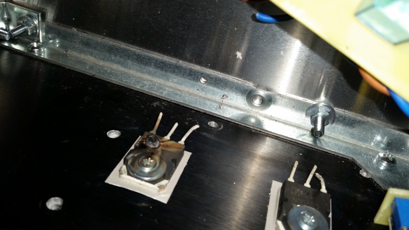
Doesn't Q8 need to be attached on Q6? ,Yes
Last edited:
DX is not fine.thank you very much for reply.
I think that adding all that stuff you suggested could solve the problem, but I can't understand why the other realizations of dx amp work fine but not mine. Adding emitter R means solder them under the pcb and cutting copper traces, and the same for the miller caps on tip...
I think I will leave this project. I have a pair of pcb ready for DX BLAME amp and all related components buyed on digikey. the transistor I have are MJL3281/Mjl1302.
Or I could realize another class AB amp, stable and with no problems...have you got any suggestions? I was looking at symasym amp (I realized it in the past and it worked good, but I didn't like the sound ver much
I have all the components for symasym, I miss only mje15030/15031....
I'll appreciate any suggestion to listen and enjoy some music,....help me please
It has severe ringing and in extreme cases this develops into oscillation. The Design is bad.
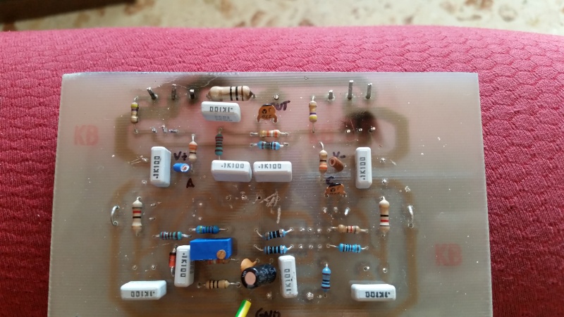
The PCB layout is worse. It is terrible.
I can actually measure the ringing and ripple along the extended "ground" trace that runs around the PCB.
- Status
- Not open for further replies.
- Home
- Amplifiers
- Solid State
- Destroyer x Amplifier...Dx amp...my amplifier