Hi dear DX,
The circuit I mentioned is not a SMPS, but it switches anyway, he, he...
http://picasaweb.google.com/lh/photo/rOgiSl8IVgPdqOcKLPkbNA?feat=directlink
I will use -ECdesigns-' own words to explain the circuit I robbed him for high power purposes...
I did not add yet the capacitance multiplier part of the circuit ( built until C2).
He has a potentially better "floating" version also.
http://picasaweb.google.com/lh/photo/UyHCdD9B2QkYmc8HPORBqg?feat=directlink
All active parts' values have to be increased to meet high power/high voltage demands.
I have posted a photo of this mod on the DX HRII thread before:
http://picasaweb.google.com/lh/photo/if0Yt3ku1R4vGDMHNErStA?feat=directlink
This mod enhances transparency, detail, and all the goods you mentioned about AKSA, but the bass and warmth became lesser (probably psychoacoustic effect of increasing the high of the spectrum). Now I am slowly increasing the bias and the warmth returned. I am now at +/-127mA for 630mV at the bases of the power transistors. Today I planned to go to 640mV at the bases.
The mod is done as per the schematics because I am not able to optimise it myself...
Best regards,
M.
The circuit I mentioned is not a SMPS, but it switches anyway, he, he...
http://picasaweb.google.com/lh/photo/rOgiSl8IVgPdqOcKLPkbNA?feat=directlink
I will use -ECdesigns-' own words to explain the circuit I robbed him for high power purposes...
> First the primary smoothing cap (Cp) is charged with the polluted rectified voltage through D1 ... D3. R1 puts a positive voltage on P-FET T1, switching it OFF, and disconnecting the load during this charge cycle. All interference surges through the primary smoothing cap -not the connected load- The severety of the pollution really doesn't matter at this point, main purpose is to get the primary smoothing cap Cp charged.
> Next the rectified voltage drops below the voltage across the smoothing cap Cp plus voltage drop across the rectifier diodes D1 & D3 or D2 & D3, now the rectifier diode no longer conducts, and interrupts the noisy charge current. All that remains after this interference attack is a charged capacitor. The P-MOSFET is not yet switched-on as -Vgs is still too low to make it conduct. Now we have a floating charged cap (Cp), it's basically similar to a battery connected to GND with the minus terminal. Needless to say that all the interference signals during charging are not "remembered" by capacitor Cp.
> As the sinewave voltage drops, P-channel MOSFET -Vgs gets high enough, and T1 switches-ON. T1 now connects charged cap Cp to both Cs and load, the charge of the primary smoothing cap supplies clean energy to both Cs and load.
> After the sinewave voltage rises again, -Vgs drops and T1 is switched OFF. Now the secondary smoothing cap Cs continues to supply clean electrical energy to the load. The cycle is repeated 50/60 times a second with half-wave rectifiers, and 100/120 times a second with full-wave rectifiers. Both D4 and D5 (Zener diode and Schottky diode) are added for protecting the gate of T1. D3 was added to create the required switching signal for T1. T1 is switched-on by pulling the gate to GND through both R1 and R2, the protection diodes D4 and D5 will limit -Vgs. T1 is switched off by pulling the gate to plus through R1. The peak charge transfer current through Cs is limited by the P-MOSFET RdsON, but can be further manipulated by adding an extra series resistor in the drain lead.
> Negative charge-transfer power supplies are very similar, just use a N-MOSFET, and reverse polarity of diodes and caps
I did not add yet the capacitance multiplier part of the circuit ( built until C2).
He has a potentially better "floating" version also.
http://picasaweb.google.com/lh/photo/UyHCdD9B2QkYmc8HPORBqg?feat=directlink
All active parts' values have to be increased to meet high power/high voltage demands.
I have posted a photo of this mod on the DX HRII thread before:
http://picasaweb.google.com/lh/photo/if0Yt3ku1R4vGDMHNErStA?feat=directlink
This mod enhances transparency, detail, and all the goods you mentioned about AKSA, but the bass and warmth became lesser (probably psychoacoustic effect of increasing the high of the spectrum). Now I am slowly increasing the bias and the warmth returned. I am now at +/-127mA for 630mV at the bases of the power transistors. Today I planned to go to 640mV at the bases.
The mod is done as per the schematics because I am not able to optimise it myself...
Best regards,
M.
maxlorenz said:
Now I am slowly increasing the bias and the warmth returned. I am now at +/-127mA for 630mV at the bases of the power transistors. Today I planned to go to 640mV at the bases.
Hi max
Not to be taken as criticism, but I have never liked to increase bias on a AB amps
I know many people say that, about sounding warmer
But to me it just sound more muffled
I have revised my plans fore my DX
I want it to maybe be usefull to other than me
Maybe even tease Carlos enough to make him build one
But time will tell, how it sounds
Its simple enough to do it with good components without too much cost raise
Good small caps and nonmagnetic resistors
Onboard supply with switchdiodes
Elna silmic, 6x 2200uf on each rail
All supply lines covered with caps
Something I have long wanted to try
Though I have good exerience with using just a single pair of supply caps
Carlos, I hope you are not too much against me removing all those 100nf film caps on supply
Still plenty questions
Trying to find whether my used BD139 are any good
I could buy new, but they are old ones supposed to be special("gold leg")
Only a few work it seems, but maybe Im not doing it right, because I get different readings, sometimes nothing, and then suddenly something again
Member
Joined 2009
Paid Member
ostripper said:I have wondered about the "thump".
OS
What causes the thump ? My TGM (following a bit Carlos DX but not DX) has no zener or LED CCS but no turn on thump.
Well.... people know me very well...i am someone that talks true!
I do not like, anyway, people making modifications into my schematic.
I really think, if people wants to make his own amplifier, them open a thread, give it another name and do not enter Dx amplifier thread to redesign or modify, as this amplifiers was already made, already tested and it is not openned to modifications, suggestions, upgrades and updates.
If you wanna modify, this is up to you...but avoid to call it a Dx amplifier, use another name, alike Dx by Tinitus... or Tinitus bootstrapp design....or "a new vision into the bootstrapped designs" but do not use this thread as a support thread to those purposes.
Dx Corporation reserves to itself the rigth to defend his proprietary designs against piracy or another kind of harmfull activity.
There's a lot of "other visions" into the bootstrapped design already made...i think Bigun has one.... my transistorized friend has other MJL21XXX and some others...this is healthy...new names, new ideas, new threads, new guys constructing.
Dx Corporation circuits were deeply tested, many guys have built... proven design (copy if you want, adaptation if you want, recreation if you want..but has some personality) tested by several folks, and the Dx Corporation will be against the use of brand name to modified circuits...this activity is not welcome.
The remotion of power one thump was a result of fast charging of capacitors into the long tail, the use of zener and low value of capacitors...this way, the voltage stabilize fast and the power on thump disappear.... and this is the only goal i have to beat Aksa..also the low end bass.... into the power on noises and basses i have smashed the Aksa 55...but my circuit loose into treble, mids and sound stage..... the magic effect into the sound stage, hugh has made...is unbeatable as i could see.
Carlos
Thank you by the nice support
There's no originality, proprietary designs in our modern world, with fast communication, with internet..the global connection was made and now we are a big village... and this will be good..to know one each other will result in more peace and better understanding between all of us.
When we build an amplifier using output emitter follower, in the reality we are not discovering things...Mr. Darlington have discovered when working for others..have not patented and died lonely and very poor...very unfair thing happened....so..when we build our amplifiers we are not discovering nothing.... almost everything was made by others first....you see zobel...you see the differential input, the sophisticated VAS from Doctor Self..some ideas from John Lyndsey Hood (JLH) and others.
All we can do in our modern world is to select some of those discoveries and put them together to see if they work fine this way..to adjust circuits to other currents, other ideas about biasing, some feedback loops, NFB can be modified to be local into each circuit or just from output to input.... you can produce regulators, stabilizers, E/I limiters, you can use zener, Leds or voltage dividers using resistances, you can shunt or blend circuits..well...all we can do, in our modern world, is to produce Frankenstein products as nothing about knowledge belongs to us.
The Engineers had teachers... we have Gurús alike Nelson Pass...this one have really created something different..and this is hard to be done.... even Nelson Pass had teachers...no one born already knowing.
So, if you wanna some place under the sun.... one spot ligth over you head dear friends..go ahead... create your own... but open your thread, give it a name and go ahead beeing happy and contribute to our communitty.
But let Dx Amplifier, original design, in peace.
regards,
Carlos
Attachments

I am enjoying DVD movies and home teather sound in my living room
i am not creating things those days...just having fun with movies.
Pre amplifier is something i do not use, as we can adjust power amplifier sensitivity to all kind of audio sources....less stages inside the audio chain means better sound.
A good headphone and one transistor class A, low current stage, in series with your headphone cartridge is the best possible sound we can have... each part plays a lot into the audio result..reducing parts you gonna reduce losses in quality.... observe the transistor drives some miliamperes....and low voltage too...the headphone is in series with colector to emitter circuit.
I use a potentiometer into the power amplifier input to control the volume, and that's all i use.
regards,
Carlos
Carlos, my food loving friend, have a bite
I respect your curcuit
But will make it very small
Fore mid/tweeter
Or fore speaker with high sensitivity
I will not change anything
Need to buy new BD139
Thought I would look at other option, just to see, and learn
Found several
BD237, BD439, BD441, MJE180 etc
But somehow TIP14/42 still seems to be hard to beat
Also not sure why to use faster ones, that will need to be "slowed down" with more components
Others dont like BC###
Well, they seem to work fine in F5 too
Ehhh, original 2N5401 is PNP, and the substitute BC### is NPN, or did I get something wrong
Attachments

Italian Spaghetti al sugo is very nice
But today i gonna have brazilian Feijoada. (phey-joe-ah-dah)
Black beans with salt and garlic and a lot of meat inside... meat cook inside..some special portuguese sausages, bacon and jerked meat.... traditional Brazilian food created by slaves.
Down the sixteenth century, slaves created this food with some meat masters dislike..alike pig ear, pig foot, fat alike bacon...pig skin and those things..so they have mixed with black beans (have to be the black ones) and together white rice, some green vegetable sliced (spinach..that popeye food) and orange (yes..pieces of orange in slices.. the acid ones!) they have created a very special and delicious combination.
The farmer owner... the slave master, the slave owner, wanted the best meat parts from the pig..no bonds no ears and so on...they used exaclty those parts to the feijoada..now a days it is more sophisticated..only those meats i told you.
Alike Strawberry and Cream dear Tinitus..some mixing of food combination...mixed... result in delicious flavors.
No picture...i have already eated all i had..hummmmm... delicious
regards,
Carlos
This is what I hope to achieve
Just have to squeeze in the DX curcuit
Several building consideration
We have become used to double sided and through hole plated boards
In my youth when I built my first amps, there were no such thing
Single sided boards needs special building attention
You cannot just solder a wire or component from topside
One could use solder lugs
But I dont like that, as bottom soldering easily gets disturbed
Well, mmaybe one could use different higher heat solder the lugs to board, and "softer" solder fore later soldering on lugs
A bit too complicated
Another point is mounting of power transistors and heatsink
Cant do it without good old heatsink angles
Makes building much easier, logic and solid
I usually NEVER use connectors
But fore this it is the best option
Attachments
The ones that wants to modify the Dx Amplifier
create another brand name because your modifications and open another thread to expose your amplifier.
This thread is for the original, standard and non modified Dx schematics.
No, negative, i am not angry...the canon is there "just in case" the guy insists.
regards,
Carlos
create another brand name because your modifications and open another thread to expose your amplifier.
This thread is for the original, standard and non modified Dx schematics.
No, negative, i am not angry...the canon is there "just in case" the guy insists.
regards,
Carlos
An externally hosted image should be here but it was not working when we last tested it.
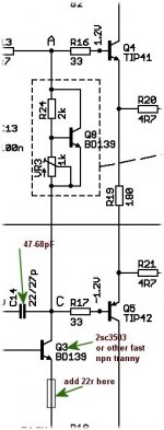
We don't mess with canons here,carlos... too small , this is what we make here...  Knoxville,tenn.
We don't use TIPs - BD's here , fairchild KSA's are cheaper, faster.
so with a little 22 ohm resistor , more people can build DX's (or call
it a DX+ , or a better amp, or whatever.)
It seems in europe / S. america ,BD's are more widely used , here is MJE , KSA/C , MJL.
OS
Knoxville,tenn.An externally hosted image should be here but it was not working when we last tested it.
We don't use TIPs - BD's here , fairchild KSA's are cheaper, faster.
so with a little 22 ohm resistor , more people can build DX's (or call
it a DX+ , or a better amp, or whatever.)
It seems in europe / S. america ,BD's are more widely used , here is MJE , KSA/C , MJL.
OS
Quotes from NelsonPass
PassLabs forum, "B1 buffer preamp" thread
Post 1700
"I always enjoy seeing what you guys come up with - occationally I learn something also"
No doubt a great man, with a big hart
Carlos, I do know that you will have visits from more wild "cowboys" than Pass forum, and have difficulty controlling the thread
But noone owns a thread, or decides whats said
Thats whats sticky threads are fore, I guess
Or "www" links to home sites
"Ontopic" posts may be relative, but anything concerning DX should be considered on topic, and valuable
Its the only way a forum moves forward
Or else it would be on standstill
That was my objective version
I have Cviller F5 boards on my desk and PeterDaniels F5 coming
Also matched optocouplers from udaily, fore "lightspeed" att
And other stuff you know of
And some speaker projects
If my approach trying to do a nice DX amp makes you that unhappy, then I feel like wasting my time
But it was fun though, and I did learn some
No hard feelings
Cheers
Member
Joined 2009
Paid Member
tinitus said:I respect your curcuit
But will make it very small
Fore mid/tweeter
Or fore speaker with high sensitivity
This sounds fun, how small can we make it - I challenge you to make it smaller than my TGM pcb, which is single sided through hole and no links ! (and it works of course)

Originally posted by Bigun
This sounds fun, how small can we make it - I challenge you to make it smaller than my TGM pcb, which is single sided through hole and no links ! (and it works of course)
Designing a small board is just as challenging as assembling one...
Hi all
I will respect Carlos whishes not to do this here, whether he is right or wrong to take that position
I have mailed to ostripper about making our own "DX modded" thread, or whatever we should call it
As per Carlos suggestion
It could seem very strange to do this, suggesting yet another thread, but it is Carlos own suggestion
I certainly hope to see Carlos participate there too, if he wish to
This is intended to be a valuable attempt, and nothing else matters
It is by no means thought as a provocation, but only intended to be a positive act
I see DX as a good DIY project
Even if its not about advanced curcuit design, there is still lots of work fore the less skilled
Its not just a premade kit
Its still a lot more work than just kits assembling
I just dont think it should end there
It may end as quickly as it started, or even lead nowhere at all, but thats only up to us
No matter how it turns out, I will accept it
Without support I will not do anything
cheers
- Status
- Not open for further replies.
- Home
- Amplifiers
- Solid State
- Destroyer x Amplifier...Dx amp...my amplifier