Hi Meanie, Carlos is trying to start a little business in brasil selling DX amps... So , I would preffer not to flood the market with too many options until his business is a bit more stable.
I would be willing to send you a personal copy of the layout though, as you have been supporting our group buys since day 1.. of course (especialy knowing you have trouble makeing payments without CC and paypal), I need to wait for permission from Charly first.
But, as explained above, I can ont release these baords at this stage to the public in good conscience.
I certainly see a gap in the range for a revised board that can handle a bit higer rails than the 2 first amps, and a bit less than the Precision I.. say something in the 40 to 55V range...
The board however was more a showpiece, and to find a use a for all the scraps of PCB I have... And of course to inspire people to try their own versions.
Carlos went through alot of trouble explaining to some folks how to get their setups working with a bit more juice than the original schematic called for.... I never saw any of those boards completed though, allthough we had some reports of it.
P.S. Hi Harry, another old supporter.... I'll check out the PSU thing for you...
Nordic,I can wait;I realy like the layout of the DX.Maybe later the payment prob is solved but for now it isn't.I've to build my HRII also but the DX layout is welcom if you get the permission from Charly.By the way what kind of program are you using to design your boards?Nordic said:Hi Meanie, Carlos is trying to start a little business in brasil selling DX amps... So , I would preffer not to flood the market with too many options until his business is a bit more stable.
I would be willing to send you a personal copy of the layout though, as you have been supporting our group buys since day 1.. of course (especialy knowing you have trouble makeing payments without CC and paypal), I need to wait for permission from Charly first.
...
Fine, send the the data, just avoid to publish layout for a while
Also, please, avoid to give gerbers or publish gerber for a while.
Soon we gonna be more free to publish those things.... a matter of 2 monthes only.
I am making a test here, and even without boards, as they have not arrived from factory, i am already have people that copied from Greg site and producing and selling in the South of this country....so, there's a real risk here.... i really do not know if my business down in Brazil will suceed.
regards,
Carlos
DX HRII Initial Startup (Troubleshooting Time!)
Well...I'm powering up my first channel today and here is what I get:
The resistance between Servo+ and Servo- is 3k
The voltage between Servo+ and R16.1 is 495mV
The VBE for the 2SC5200 is 492mV
The VBE for the 2SA1943 is 750mV (and bouncing around rapidly)
The voltage between GND and OUT is 20VDC!
The 10R 10W cement resistors (in the fuse positions) on the voltage rails get VERY hot after a few moments.
The torodial transformer is buzzing a bit (especially during the first 15 seconds on and when I'm probing for voltages)
R28 is 3k6 fixed
R7, R21 are 100r
R18, R20 are 220r
C21 is 47pF
The output devices are Toshiba and sourced from Mouser...hopefully they are the real thing!
Any ideas?
Hello Sir,
A1943 seems to have a problem.
Indeed, vbe = 0,75 V is too big, too big for linear use.
Look for Vce, Vcb and voltage across base resistor ( ie Ib ).
* Vce ~ 0,2 or 0,3 V : sature transistor.
* Vbc = 0 : transistor can not work
* Resistor voltage / Resistor value < ICmax / hFE
A1943 seems to have a problem.
Indeed, vbe = 0,75 V is too big, too big for linear use.
Look for Vce, Vcb and voltage across base resistor ( ie Ib ).
* Vce ~ 0,2 or 0,3 V : sature transistor.
* Vbc = 0 : transistor can not work
* Resistor voltage / Resistor value < ICmax / hFE
Re: DX HRII Initial Startup (Troubleshooting Time!)
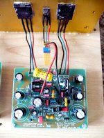
Here is a photo of the completed channel:
http://picasaweb.google.com/salesmonster/DXHRIIBuild/photo#5176919825869539890
Whatever is going on, it seems that I was consistant. Both channels are doing the same thing.")
Here is a photo of the completed channel:
http://picasaweb.google.com/salesmonster/DXHRIIBuild/photo#5176919825869539890
Whatever is going on, it seems that I was consistant. Both channels are doing the same thing.
I had simulated many possible errors, possible human mistakes
inverted transistors, shorts, wrong resistances, open circuits.
The only error i found that could make 20 volts into the output is the use of PNP transistors (BC556) instead of NPN transistor (BC546) in this position.... correct is to use NPN units here.
Good luck..for sure you have error.... and good that your error is consistent...so..finding one channel, the other will be fixed at same time.
Of course there are other possibilities..but this is one the deserves you to check.
Check for oscilations too...your transistor wires length are too much big.... already entering the "dangerous size"....so, measure AC into your output, to check if you have oscilations, also check the zobel resistance to see if it is hot.
regards,
Carlos
Attachments
Please, reduce those wires length...those ones from
power transistors to the power amplifier boards.
Install your boards near the heatsink, this way your wire will be shorter...cut them to half the length you have now.
Heatsink can have ground wire....main ground...the transformer center tape, not the input lifted ground.
regards,
Carlos
power transistors to the power amplifier boards.
Install your boards near the heatsink, this way your wire will be shorter...cut them to half the length you have now.
Heatsink can have ground wire....main ground...the transformer center tape, not the input lifted ground.
regards,
Carlos
Attachments
Thanks for the replies.
I could have easily mixed the transistors. I tried to keep them separate, but once I had the heatshrink around the pairs all bets are off. It wouldn't be the stupidest thing I've ever done by a LONG shot.
I will pull them tonight and see what they are. Thankfully, I bought 50 of each a while back for matching.
I hope this is your problem..this way we gonna have a working unit
that will make both of us smile a lot.
Keep me informed, i will continue to search into the simulator, to make wrong things till if found your 496 milivolts into the VBE multiplier colector to emitter (confirm that please) and 20 volts positive into the output..confirm that also.
I hope we will have it working soon.... at least i will be working on that with you.
I use to make those mistakes, almost twice a week...and in the past was daily...so.... those things do not surprises me, and i do not think i am too much bad in electronics because of that... at least i do not give up...i continue to make daily "ship" and fixing them daily...you know a ship carried with my errors listed in paper...rolls of paper...rolls! ..ahahahahah.
regards,
Carlos

Floorplanning and transformer selection
Hi,
With the help from PCBs and a component kit from Nordic I'm in the process of putting together my DX HRII Amp. Currently I'm working on the case, transformer and heatsink selection to get all the major pieces in place.
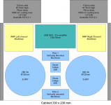
I'm leaning towards a case from Autocostruire, 230x280x80mm in size. The idea being this project is to design a small setup to go along with mediacenter in our livingroom, so I want the smallest case possible to hold the components.
I have attached a picture of two alternatives:
Any feedback is welcome. Each heatsink is roughly 1000cm² which based on some ealier post from Carlos should be "in the ballpark". I know that the two transformer setup is better then the single transformer case, but I'm not sure if I really need it. A single 500VA transformer will make the case less crowded, easier to assemble and cheaper.
I'd also like some recommendation on the proper secondary voltage for the transformer, the options I have seems limited to 2x25V or 2x30V AC. This results in either too low (34V DC maybe) or too high (41V DC maybe) voltage based on the recommendation of +35V to +37V DC. Which way should I go? My speakers are 6 ohms.
The USB DAC drawn in the picture is a future project, pay no attention to that board at this point.
Regards from a snowy Sweden!
Daniel
Hi,
With the help from PCBs and a component kit from Nordic I'm in the process of putting together my DX HRII Amp. Currently I'm working on the case, transformer and heatsink selection to get all the major pieces in place.
I'm leaning towards a case from Autocostruire, 230x280x80mm in size. The idea being this project is to design a small setup to go along with mediacenter in our livingroom, so I want the smallest case possible to hold the components.
I have attached a picture of two alternatives:
An externally hosted image should be here but it was not working when we last tested it.
Any feedback is welcome. Each heatsink is roughly 1000cm² which based on some ealier post from Carlos should be "in the ballpark". I know that the two transformer setup is better then the single transformer case, but I'm not sure if I really need it. A single 500VA transformer will make the case less crowded, easier to assemble and cheaper.
I'd also like some recommendation on the proper secondary voltage for the transformer, the options I have seems limited to 2x25V or 2x30V AC. This results in either too low (34V DC maybe) or too high (41V DC maybe) voltage based on the recommendation of +35V to +37V DC. Which way should I go? My speakers are 6 ohms.
The USB DAC drawn in the picture is a future project, pay no attention to that board at this point.
Regards from a snowy Sweden!
Daniel
Hi Daniel,
I'm no expert, but both configurations look good to me. If you use the smaller voltage, then the dual transformers would fit easier since the toroids would be physically smaller (obviously). But I would also have no problems using a single transformer.
The single transformer configuration allows more room for bigger power supply capacitors. I don't see any in your drawing. Are they on Nico's PS boards?
I understand the power supply rectifier diodes might inject some noise into an input circuit if it's too close, so for that reason the single transformer layout would have a slight advantage. But I don't know if that's a real concern.
The voltages are close, so you'll probably just have to adjust the values of the series rail regulator zeners up or down a couple volts to keep everything happy. Without changing them, going up in supply voltage (41v) would provide more regulation for the input circuits (maybe too much), and going down (34v) would provide less (maybe not enough). Carlos would be best to advise you on that concern.
Keep us informed of your progress!
..Todd
Good ideas you are showing us
I like them very much.
the Bigger voltage transformer you have will be better, the bigger voltage option will be better, as you gonna have losses, and this increasing in voltage (the 30 volts transformer), will be good
Of course, the zeners will need to be adjusted, those zener diodes works in series, they add one to each other, say, two units of 12 volts result in 24 volts.
You may need to adjust your diodes to 3, 4 or 5 volts lower voltage than the power transistor colector voltage..... and the power transistor colector voltage means the supply voltage.
This will depends how much you trust into your supply transformer, how big and huge it is...if you decide to use one transformer only, better to use 5 volts lower voltage zeners, for sure you gonna have this drop of voltage (or more!) when both amplifiers starts to pumb bass.
Go back, some posts, in this same thread, i have published a simple way to test transformers under load conditions, to see how they perform, this is something very usefull to decide the correct zener diode voltages.
regards,
Carlos
Updated floorplan
Hi,
Thanks for the feedback! I realized a misstake though... The 280x230mm case I was hoping to buy would end up with the front panel on the wrong side of the amplifier (the case was deeper then it was wide). So I need to purchase the 330mmx230mm case to get the correct orientation, see updated attachment.
The two PSUs have 4x 4700uF/50V caps each, these caps are available in 30mm diameter which are only 25mm tall. This allows placing the PSU PCBs vertically as drawn in the picture. I hope I didn't forget any other potential tall components on the PSUs, I assume the big caps would be the tallest ones (except for the terminals).
Regarding the zeners I will start with 20V+18V=38V which should be 3V below the anticipated 41V minimum from the transformer (probably more then lightly loaded). Carlos, I will find your post once I have the transformers in my hand!
With the new case there seems to be some room left over for 2x250VA toroidal transformers so I will probably go down that path. Leaves enough room for the rectifiers attached to the bottom as well (for cooling).
Regards
Daniel
Attachments
About my post, loading the supply and measuring
I have posted but do not remember where, as i post in many places, including brazilian foruns, a Blog and Orkut too.
There are three main threads, the Dx Amplifier, my amplifier,
The Precision thread
And also one thread Nico have opened about HRII, the group buy.
So, those informs may be in one of those ones, sorry not to give you more precise informations.
But...in advance, the idea is to place a resistance, to drain the current you will have consumed by your amplifier, worst case, undistorted power, sinusoidal and over 4 ohms...continuous, steady tone...so.... you can calculate (ohms law) the resistance and put it into the positive to ground and negative to ground, to see the voltage you will have draining a good current.... and the current and voltage we will know doing the testings, as the supply will have drops of voltage.
So, for instance.... if you conclude your amplifiers, together, will need 8 amperes, when both working into a single transformer supply, into a single supply, then you can use 7 ohms or something alike that... fast test...connecting from positive to ground one resistance (carefull, use 10 watts and do this test very fast do avoid resistance to melt down or burn something) and connecting another one from negative to ground..then install the voltimeter to see the voltage you will have over this load.
This way you will evaluate your supply, you will know the voltage you will have when your amplifiers will be operating full undistorted power, you will realise the swing of voltage you will have into the supply, this may modulate your audio...very bad that swing, but we can be free of that, at least into the input circuits using the series regulators provided into the HRII, and they play a lot into the result of audio quality..
The voltage you will have, draining many amperes, at least 4 amperes each rail, simultaneously sucking current from both transformer secondary coils, and them reduce 1 or 2 volts and adjust your zener to that voltage.
Yes.... the lower the zener voltage, the lower will be your power, but quality of audio will increase, it is clear when you advance the volume, the sound comes without distortion!.... a good 35 watts amplifier (each channel to 8 ohms) can sound very big if undistorted, as you will use the whole power, having not the peaks distorted together your sound, not modulated by the voltage swings..the big hell to the input circuits, even when they have CCS, current sinks and all stuff, when not stable the voltage you feel the sound "dirty".... "poluted", not clear, not crystal clear.
I hope you understood...i know my english is awfull, but try a little, if could not understand...please, ask me again..if shy to post here, go to
panzertoo@yahoo.com
and i will use audio, images and other words to explain you, gladly.
regards,
Carlos
Attachments
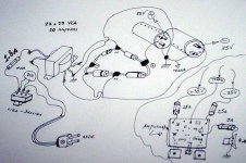
You may have those sketches in English, and maybe better images somewhere in
our threads.
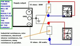
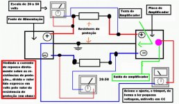
Here is something usefull, the care about fuses (highly suggested)
and a very simple supply, the sketch to beginners (not your case, was made do Brazilian forum, this is high tech there!)
Do not be offended, please, have no bad intentions, i know those informations are very basic, but we have beginners here too, they are hidden, but they exists.
Sorry folks... do not know if "somewhere" is written this way or "somewere"...sorry..will study more!
regards,
Carlos
our threads.
Here is something usefull, the care about fuses (highly suggested)
and a very simple supply, the sketch to beginners (not your case, was made do Brazilian forum, this is high tech there!)
Do not be offended, please, have no bad intentions, i know those informations are very basic, but we have beginners here too, they are hidden, but they exists.
Sorry folks... do not know if "somewhere" is written this way or "somewere"...sorry..will study more!
regards,
Carlos
Attachments
Hi Carlos,
Thanks for the information, if I understand your concern regarding the fuses correctly you are trying to point out the fact that the resistance of the fuse (including holder) is important in order to not get a voltage drop across the fuse. I looked up a 6,3A 5x20mm fuse from my supplier including holder and the total resistance including holder is in the order of 14milliohms which seems ok.
In the power calculation side I know the theory pretty well but I'm not sure how it applies to audio amplifiers. I attempted two calculations, one targeting 75Watts into 6 ohms and one for 100Watts into 6 ohms.
75 Watts into 6 ohms = 21.2V RMS (30V peak) to speaker
21.2V over 6 ohms = 3.54 A RMS (5A peak) to speakar
41V DC from supply * 3.54A (RMS) = 145VA (for high frequencies)
41V DC from supply * 5A (peak) = 205VA (for very low frequencies approaching DC)
100 Watts into 6 ohms = 24.5V RMS (34.6V peak)
24.5V over 6 ohms = 4.08 A RMS (5.78A peak)
41V DC from supply * 4.08A (RMS) = 167VA (for high frequencies)
41V DC from supply * 5.78A (peak) = 237VA (for very low frequencies approaching DC)
Does these calculations make sense? Seems that a 250VA, 2x30V transformer should be able to handle 100Watts into 6ohms in theory, assuming only a few volts of headroom is enough for the output transistors in the amp. I'm sure this is not the case though, so where is the limitations in reality?
Once I get the transformers in hand I will attempt to load them and measure the voltage.
Thanks
Daniel
- Status
- Not open for further replies.
- Home
- Amplifiers
- Solid State
- Destroyer x Amplifier...Dx amp...my amplifier