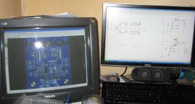
Nice, I also have a Dell 2007WFP, wich is a 20" wide that can rotate if the need arises... (very seldomly) from a productivity point working with programs like dreamweaver and photoshop the extra width to fit toolbars in, also helps heaps. I'd be hard pressed to buy a 4:3 ratio monitor again... I use a 17" CRT in dual screen format with my LCD... Analog meets digital. 17" works nicely with the 20" wide as they are the same height. for those who dont know how wide a 20" monitor is.. it is as wide as your keyboard (not 20") looks smaller in photo due to paralax error, it is about 20cm back from front screen... I have a 19" CRT as well, but is not connected. just too huge for my desk.
My native resolution is 1680 x 1050, which is very crisp. On PCs the 16:9 stuff is limited to apple's offerings, I think... the LCD panel in my monitor is the exact same type apple uses in one of their monitors.
My native resolution is 1680 x 1050, which is very crisp. On PCs the 16:9 stuff is limited to apple's offerings, I think... the LCD panel in my monitor is the exact same type apple uses in one of their monitors.
Attachments
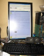
Wonderfull equipment you have...i have a tiny 15 inches Samsung SyncMaster 551V
Nordic..... i have dismounted my HR-II.... the prototype.... too much messy, and i am constructing other.
The heatsink was sanded and painted back once more...and i will arrange something less awfull to show you in the future.
I am busy.... things to do here, a move to another appartment..well...life is very confused those last days.... so.... the new one may delay some time
Also i will be out from the air for a good period of time to be plugged once more into the WEB into the new appartment.
The voltages are almost the same.... differences not important, as they are under 10 percent..some of them 20 percent maximum.
The new High Resolution II has different bootstrapp, but if you add both resistances you will perceive that the current and voltages will be almost the same you have into the standard Dx that already operates with 35 volts (37 mine unit)
The modifications goes to differential colector load, there, you will have 1.2 volts ( I suppose) that will feed the VAS input transistor...the VAS current is the same and VAS transistors have 580 milivolts from base to emitter.
So..follow the standard Dx voltages and you will be informed about the voltages needed.
The bootstrapp is using different ratio of resistances..but if you add them together you will see the diference is small.. a different bootstrapp action i have now, but, current and voltages, into stand by mode are almost the same.
I have not unit constructed..heatsink drying paint...will delay 2 days to dry..and i think i will delay more to construct other board because i am busy.
If you need some current, or voltage in special...not beeing too many, i will be able to check that into the simulator HR-II sample i have here..but no real voltages, that use to be a little different.
regards,
Carlos
Nordic, you clearly know what you are buying but consider for a moment the poor people who end up with a 17" wide screen. Carlos, your 15" monitor is far more practical than one of those.
Carlos, I hope every thing works out fine and that you are not away for to long. We'll miss you.
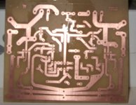
Anyway, not the best picture in the world, just finished and still wet. It makes me smile at least......
Carlos, I hope every thing works out fine and that you are not away for to long. We'll miss you.
Anyway, not the best picture in the world, just finished and still wet. It makes me smile at least......
Attachments
Ecat,
You have done a very nice PCB, looks great!. Only one thing worries me though, the PNP output collector trace seems very close to the base and emitter trace which I could see as being a potentially displeasing situation if they were to short together after soldering, definately one place to check before firing up. All in all though looks well thought out and I can see it getting even more refined as Nordic and others pick their way through it again and again") . As Carlos has stated, you should find this to give a good amount of Audio satisfaction in its closer to the source sonics.
. As Carlos has stated, you should find this to give a good amount of Audio satisfaction in its closer to the source sonics.
Colin
You have done a very nice PCB, looks great!. Only one thing worries me though, the PNP output collector trace seems very close to the base and emitter trace which I could see as being a potentially displeasing situation if they were to short together after soldering, definately one place to check before firing up. All in all though looks well thought out and I can see it getting even more refined as Nordic and others pick their way through it again and again
. As Carlos has stated, you should find this to give a good amount of Audio satisfaction in its closer to the source sonics.Colin
.... so, you will be the pioneer
Since my delivery failed to appear that depends on how many spare parts I can find around the place. But, I think I may be able to get something working To be honest for this board I'll be happy if most of the parts simply fit.
For the version 0.2 board I'll enlarge your name, top right in the pic. I'll also remember to mirror it before printing
Best wishes once again Carlos.
Colin,
Thank you.
Your concerns noted, thanks for the input. As I said above I'll be happy just to see the parts fit, I'm sure some will have to move. Nordic is doing some beautiful work, he is quite the pcb artist. I just auto route As for eventual sound ? Well, Carlos would not have published the design if it were not something special. I have every faith.
Since my delivery failed to appear that depends on how many spare parts I can find around the place. But, I think I may be able to get something working
To be honest for this board I'll be happy if most of the parts simply fit.For the version 0.2 board I'll enlarge your name, top right in the pic. I'll also remember to mirror it before printing
Best wishes once again Carlos.
Colin,
Thank you.
Your concerns noted, thanks for the input. As I said above I'll be happy just to see the parts fit, I'm sure some will have to move. Nordic is doing some beautiful work, he is quite the pcb artist. I just auto route
As for eventual sound ? Well, Carlos would not have published the design if it were not something special. I have every faith.Thank you Colin...also Ecat
I am entirelly sure that this amplifier is absolutelly special in sonics.... a step up in sound perfection...will produce enormous pleasure.
the triple guarantee will be increase to four separated guarantee soon.
I am happy that you want to print my name there.... more happy i will be watching other boards printed.
DX HRII, by Ecat.
You made the boards, a nice work, and i will be happy to have a part of this pride together you.
regards,
Carlos
Re: Increase the differential colector resistances to around 2K
Hello Carlos
I did look at Dr Self blameless amp web page, and in his VAS he use a 100pf miller capacitor, a bit high value, and he don't use a capacitor across the NFB resistance.
Your VAS are better since you use a lower value miller capacitor, a 27pf miller capacitor, and a 10pf capacitor across the NFB resistance, I presume that your solution give a lower distortions at high frequency and maby a better phase linearity ?
Can I use my BD139 for the two transistors of your new VAS ?
That new VAS are a simplier modification that I can ad to the Dx standard schematic, so I would do it and keep the same diff input, but will use bigger cap on the rail near the diff input transistors.
Thank
Gaetan
destroyer X said:
And install the VAS shown into the High Resolution.
This VAS came from Doctor Self, and resulted excelent into Dx standard and into the High Resolution.
The VAS is constituted into two transistors, you can see it into the last schematic made by Ecat and into the schematic that has green and blue border.... frame may be the correct name.
Only this VAS inclusion will produce the results...better sound stage and better sonics... the differential arrange into resistance were made because to this VAS, to supply a good voltage to bias the VAS input.
regards,
Carlos
Hello Carlos
I did look at Dr Self blameless amp web page, and in his VAS he use a 100pf miller capacitor, a bit high value, and he don't use a capacitor across the NFB resistance.
Your VAS are better since you use a lower value miller capacitor, a 27pf miller capacitor, and a 10pf capacitor across the NFB resistance, I presume that your solution give a lower distortions at high frequency and maby a better phase linearity ?
Can I use my BD139 for the two transistors of your new VAS ?
That new VAS are a simplier modification that I can ad to the Dx standard schematic, so I would do it and keep the same diff input, but will use bigger cap on the rail near the diff input transistors.
Thank
Gaetan
Attachments
Hi Carlos,
The Beta Enhanced VAS that you are using was also used by KRELL in the KSA100 albeit though in a balanced design from input to output, so there definately some lineage commercially and judging by the nostalgia shared for those krells of past should say something . I have a good sense of what you are hearing sonically as I got to experience a great deal of it when I built and tweaked the Blameless design some months ago, and at the same time working hard at trying to convince you that it is not as bad as you once thought it was, haha. The series regulators that you are using are simple, but they do work well, I use something that shares similarities in the pre that I built but with a few twists. Welcome to the other side my dear friend, lol.
Colin
Yes...for sure an evolution Colin...if you wanted me to tell folks you have told me
So...
Yes Colin...you have told me, in advance, that blameless could sound good after tweaking...you have discovered in advance related me.
Folks...i want you to know that Hugh Dean, the Master, decided to research and develop a new amplifier together Mr. Colin...because of his efforts, cooperative spirit, excelent hability, capacity, to analise sonics with precision.... the Soraya Lifeforce born.
Not only because of Hugh ideas, but also, because of Colin Brown.
I have never listened a better sound amplifier... the best one is this Soraya amplifier.
You are happy Canadiens.... and be proud by your Colin Brown.
regards,
Carlos
.......................................................................................................
Gaetan
I like you way to do things.... very humble, even beeing a moving Encyclopedia of Audio.
Thank you by the confidence and the preference.
But i really think, you are able to design and produce things so good as i can...... and also i believe that can do better....and this would be more options to our forum, and your selfdiscovery too.
I feel good watching you just copying...i did it for more than 40 years (45 to be precise)...it is time, also to you, to hold the calculator machine and put your imagination and experience into some practical work.
regards,
Carlos
The High Resolution, as the constructors will perceive, will shock you immediatelly
because the extremelly clear, present and near perfection sonics.
You will feel the need to kiss me so gratefull you will be...but please!..i am already married..and i like kisses only from girls..ahahahahahah!
But, as everything, has room to much more corrections, upgrades, updates, transistor replacement, capacitor adjustments, inclusion of new circuits and ideas.... nothing is good enougth that you cannot tweak a little for sonics, tuning it to your preference and equalizing it to your room, speakers, ears, type of music and personal human sensitivity to some tones that are harsh by it's own nature.
Of course, the High Resolution II can turn even better using a different circuit into the input....something alike Cyrus...also CCS can be in place there too.... or, at least, the zener diode can be substituted by an electronic regulator, and also referenced into negative line to avoid difference in consumption, into stand by mode, measurable into positive rail compared to negative rail.
The bootstrapp, something i like the sonics, can be switched to a mirror, a constant current source...this way...people can listen and decide the one prefer.... a double feature, included into the board.
The input can receive bigger stabilized voltage, using another supply with higher voltage and electronic stabilization made better and having an error amplifier.
Output can use bigger transistors, and parallel units, with diode protection, coil can be removed this way... and even facing strange loads, the unit will survive...when Dx standard would die.
VBE multiplier can be modulated, and this may produce interesting results.
A positive regulation electronic supply can be used to the output.... having peaks of current, detected into the input, the power regulator can increase the power supply voltage...this may produce an interesting dinamic increaser...or dinamic power booster.
Well..there are , always, and everywhere.... ways to increase, or try to increase sonics...sometimes we run alike dog catching it's own tail and perceive that runned as a crazy and stopped in the same point you have departed...but we have to try.
In December i will try the Dx Precision..... and if published, if succeed, will eat High Resolution II.
Because of that, some monthes will be free of modifications, free of tweaks, corrections only if extremelly needed.... this way, the one (or ones) construct the High Resolution II, will enjoy their units free of the feeling that something, even better, was already made into our small part of the audio forum....better thing made into the Dx thread.
People will think.... why you insist in do by yourself, there's a lot of know how and contributions you may accept and include?
I am doing that...but i am just beeing more clever....now i am just researching over the ideas Hugh had...the circuits he suggested as good and send to his more closest friends...i am following his foot steps..... i am turning clever..... less idiot this time..following the leader now..... the Master of audio...King of sonics.
regards,
Carlos
Attachments
Thanks Nordic, much appreciated. Your layout keeps getting more and more refined
I'm rushing to find the parts I need to buy from the local store, they have limited stock, only 2 bd140's for example, and are rip-off merchants at times but I have no other option.
Perhaps I should have done this before placing the order that didn't arrive. Oh well. Just out of interest, here is a rough bom for the attached schematic.
Nothing on it has been verified, it applies only to the attached schematic and only to my layout use at own risk.
-------------------------------------------------
Code:
Vbe multiplier

Qty Value    Parts
1   2.2uF    C1      25v
1   100nf    C2

1   2k2      R1
1   1k       VR1

1   bd139    Q1

Dx HiRes

Qty Value    Parts All caps 50v unless stated

2            C1, C23 Optional big cap's
10  100nF    C2, C3, C7, C9, C11, C15, C18, C20, C24, C26
2   3300uF   C4, C27
4   220uF    C5, C22, C28, C29
1   2.2nF    C6
1   2.2uF    C8
1   47uF     C10  70v ?
1   2uF      C12
1   10pF     C13
1   220nF    C14
1   220pF    C16
1   15nF     C17
1   1000uF   C19  16v for size ? could blow in case of amp failure, 63v for safety
1   27pF     C21
1   4.7nF    C25

2   33v      D1, D3
1   12v      D2
2   1N4004   D4, D5  protection diodes, do we need these?

3   BD139    Q1, Q2, Q9
2   BC556A   Q3, Q4
2   BD140    Q5, Q10
3   BC546B   Q6, Q7, Q8

1   2k2      R1
1   1k5      R2
2   1k8      R3, R27
2   180r     R4, R16
1   4k7      R5
1   3k3      R6
2   470r     R7, R21
2   4r7      R8, R23

1   3k6      R9

2   0.22r    R10, R19   2w
2   100r     R11, R12
2   12k      R13, R17
1   10r      R15            1w
2   390r     R18, R20
1   10r      R22
2   47r      R24, R25
1   1k2      R26

1   18r      OP resistor 2w, Wind 2 layers of 25 turns 0.5 to 1mm enameled copper

1            LINK1
6            X1, X2, X3, X4, X5, X6
1   2uF   DUMMYC1     just a place marker

1   LSP10    LSP6
1   2SC5200  U$1
1   2SA1943  U$2

4   SE11     LSP4, LSP5, LSP7, LSP8
Attachments
RS components UK... Ecat...
re diodes...
since class AB current requirements vary so widely adding a (much?) larger capacitance to the output, is a must. The diode is recommended as shown to prevent the possibility of reverse biasing (and destroying) the transistor(s) when power is removed.
re diodes...
since class AB current requirements vary so widely adding a (much?) larger capacitance to the output, is a must. The diode is recommended as shown to prevent the possibility of reverse biasing (and destroying) the transistor(s) when power is removed.
VBE multiplier bypas
"How does one size this bypass?
Is the method based on time constants or impedance or sound quality or intuition or ....?"
What a great question !
For an area that is fairly low in impedance, just about every design seems to have a different capacitor value, ranging from 100nF to 47uF.
This might be one for Graham Maynard or Hugh Dean to explain ?
Regards
SandyK
- Status
- Not open for further replies.
- Home
- Amplifiers
- Solid State
- Destroyer x Amplifier...Dx amp...my amplifier