Looked at your patent now because I had thought that all kinds of shapes and sizes of phase plugs had already been tried so there wouldn't really be anything left to patent.
I was a little surprised because I don't recall seeing that exact shape used before.
Perhaps my idea of using sound absorbing material could improve your phase plug design?
edit: I would use varying densities going from less to more dense as you reach the center.
The sound absorbing materials might actually reduce the specific benefit you discuss in your patent, but might have other benefits. Hmm, I have to think about that for a bit.
Perhaps the right type of material could affect the benefit of your phase plug shape, but, do so without the difraction which would be caused by the sharp edges of your design.
It is the "Tacky Glue." That is the first bottle pictured (and not the little tube included with the Tacky Glue. There is not reason you cannot use the glues specified in my previous postings and articles. For this application, the glue characteristics are not as critical and I though the Elmer's would be more widely available.
I would recommend Kuhn's "Structure of Scientific Revolutions" even for diy loudspeaker builders. Here is why . . . Theories of diffraction and wave guides are somewhere between sort of and very wrong. Olsen's experiments, for example, were conceptually flawed and limited by the instrumentation he had to make his experiments. He made theoretical assumptions based upon the evidence he could generate from his experiments. That, however, sent him down the wrong path.
For example critofur, while you seem to believe that my plug shapes will cause diffraction effects, I can tell you that such effects are experientially absent. Also, your ideas of variable density and absorption are not important. They do not matter. They will not cause a change in performance.
While the ideas you present here are not critical, they will also cause no harm. I encourage you to experiment with your ideas. Maybe they will lead you to something new.
Now, for anyone reading. Critofur asked if my modifications would take care of the major cone problems. That question implies knowledge of the cone problems. I know from my own high resolution testing what the cone problems are. Before I start posting details about those problems, I ask the interested readers what they believe the problems may be (you might also include how you know about the problems).
Also, if you own the transducer, what version do you own? We know that TB started with the W5-704S. They may be to the "D" version or possibly beyond. How many versions are there? Check the TB label on your transducer. What is the model number? If you have something other that "S, D, or SD" please post that here. Critofur states that his "D" versions were not shielded. I hope he was not surprised by that. That seems a rather big difference not to mention to customers. If PE did not tell customers of the loss of shielding, then bad PE.
Lastly for today, I will post modifications for the transducer and provide a schematic for a crossover for use with this transducer and a tweeter. There are so many simulators for boxes, I should not have to provide this as well. If you have box ideas, I encourage you to continue to post them. If you have built the boxes and have near field measurements of the transducer output and the aperture output (assuming a ported or TL design) to post them as well. Use the same microphone spacing from cone as you do from the aperture. Do not otherwise attempt any compensation of the output measurements.
Mark
MarkMcK said:...Before I start posting details about those problems, I ask the interested readers what they believe the problems may be (you might also include how you know about the problems)...
I have not analyzed this particular cone, and I don't have any tools other than my ears at the moment (besides shop tools, that is).
I know the cone has problems because:
1) there is no material that transmits force [sound] instantaneously
2) the force being applied to the cone is not symmetric across the entire radiating surface
3) as the sound travels through the device from the beginning to the end there are multiple interfaces between materials w/different acoustic properties, and, at each interface there will be SOME distortion
4) within the pass band, the wavelength of sound in the cone material is not significantly greater than double the size of the cone, so there will be resonant frequencies in the device which are excited
5) the surround cannot terminate the wave such that the level is brought down 100%, so, there will be out of phase reflections back into the cone
6) because no man made device, other than perhaps a pure crystal, can be manufactured with absolute precision and be completely perfect, and also, because the speakers (presumably) will be mounted in an enclosure which is not completely symmetric around an axis through the center of the voice coil: there will be uneven forces acting on the cone surface which will result in stimulating the cone surface to deform (sound energy to propagate) in ways other than concentric expanding circles originating at the voice coil and expanding outward until they reach the outside edge of the cone.
#6 can be observed using a fast strobe light which can be synchronized to fire at the same frequency as a wave generator, then you observe the cone at different frequencies, and, you have a little dial to turn to adjust at what part of the wave the light flashes.
[ I believe you have more advanced measurement devices Mark? You were talking about them to me a couple times previously when we met, but, I don't remember very well exactly what the machines were that you mentioned. (aging, stress, and having abused my brain with chemicals years ago have all taken their toll, sadly) ]
---
...Which led me to believe I wanted to use Beryllium as a diaphragm material, so that a wide range driver could be "pistonic" throughout it's passband. And, also, led me to believe that the cone should be a lamination of materials with significantly different "Q"s (mechanical impedances?), because, in my experiments, I found that
such constructions DRAMATICALLY reduced resonances.
You other guys gonna try these mods? They carry Elmer's Craft Bond glue at Wal-Mart, in addition to several other similar glues, in the crafts section (usually in the back) near the yarns and such...
Pulling off the dust cap is pretty easy, once you lift up one edge with your fingernail, or some thin metal object.
If you're not very neat when you apply the glue, do you think the uneven mass could cause the cone to be less stable? If I was going to be doing that sort of thing often I would want to setup some kind of turn table and something to hold the glue applicator in the precise position... Or, maybe it would be better to make some kind of ring which you dip into a flat plate of glue then touch to the speaker.
I noticed recently that it's become common practice to have something like "wet look" or some kind of felxible glue where the cone meets the surround, or, in the crease of the surround where it's bent up/away from the cone. I got some "Modge Podge" to try in that application.
I'd like to know how much effect the "dimples" on the W6-789 surround have.
I'm guessing that when the cone interfaces with the surround the opposing force causes the cone to flex -> resonate in an adverse way and using your measurement techniques you've found exactly where to apply some mass to reduce that.
Do you know if it's simply having the mass added in that location, or if the glue changing the Q of the cone in that section has a significant effect?
edit: oh, btw, I just ordered the book that Mark recommended.
Do you know if it's simply having the mass added in that location, or if the glue changing the Q of the cone in that section has a significant effect?
edit: oh, btw, I just ordered the book that Mark recommended.
Zaph said:Does never work for you? It works for me, I'm a bit too busy these days to tackle every project I wanted to do.
I've got 12 W5-704 woofers in my closet that I've always wanted to do something with, but I'll probably just sell them.
Zaph, that wasn't addressed to you really, I'm sorry. I understand about being busy, and you've got a new family!
I just wanted to *poke* at Sreten for fun.
It's great you still share when you have a little time to poke up something interesting.
I'm sure you'll want to have your own shot at designing an excellent + high value open baffle system within the next year or so.
Since Mark's mods are so easy to do, and you've got gobs of W5s, maybe you'll throw one on the test baffle.
It's easy to make, but, if you want, I'd be happy to send you some "phase plugs" for the W5...
It's easy to make, but, if you want, I'd be happy to send you some "phase plugs" for the W5...
Thank you for putting the p word in quotes. The plugs I design have nothing to do with phase. I would be happy to just call them plugs.
I am just about finished verifying the mod. I still need to do the crossover.
As Critofur has stated, the modification is inexpensive. As others have already stated, the W5-704 (S or D or whatever) is also inexpensive. The tweeter I intend to use is also inexpensive. End result will be high quality for low cost.
Mark
I have a draft of the modification "article."
I have concentrated only on what and not why as I usually do. I know the why, but why let that get in the way.
The two-way (tweeter and crossover) is still coming. One reason it will take a while longer is because I will only publish test results of a completed loudspeaker. I do not publish simulations.
The extra time I have taken to get the mod instructions ready was because I was finding the boundaries of successful implementation. While I always suggest being as precise as possible, you can get away with a less than steady hand in applying the glue to the cone. The photo shown in the article shows a less than neat application of glue. The test results shown in the article are of the messily glued cone. There is a lot of forgiveness built into this modification. In other words, don't worry, be happy.
Here is the link to a pdf of the modification article:
http://madspeaker.com/extras/704MOD.PDF
Mark
I hope to be able to cut the baffle for the two-way design later today. Once that is done, the publication of the design should follow quickly.
Otherwise, I am still interested to see what the diy enclosure folks would come up with for this transducer. You now have the modification design and would be able to apply it and do your own T/S specification measurements.
For now, I will say that the combination of removing the dust cap and applying the glue has less of an impact on T/S specifications than the difference between manufacturer claimed specs and the specs you would typically measure for yourself. The first should not be a problem, the second is a problem for almost all of the small cone diameter transducers sourced from Asia.
Mark
An externally hosted image should be here but it was not working when we last tested it.
Hi,
A well stuffed sealed box (+sub?) is probably the best bet.
For Vas = 12L a 15L vented box can work but its not ideal,
going larger does not help much. Might suit a (ML)TQWT.
") /sreten.
/sreten.Attachments
sreten said:Hi,
A well stuffed sealed box (+sub?) is probably the best bet.
For Vas = 12L a 15L vented box can work but its not ideal,
going larger does not help much. Might suit a (ML)TQWT.
My Duo-T design uses the W5-704d in a ML-TQWT enclosure that works quite well.
Here is a thread over at HTGuide:]The Duo project
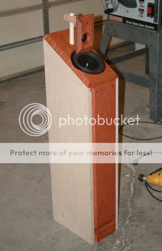
Thanks to Sreten and dineubic for the postings about enclosures. Have the sealed or ported designs been made? If so, are there any near field measurements of performance? Same question for the TL design. The enclosure aperture and transducer are far enough apart that near field testing will produce good isolation.
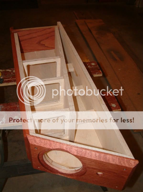
By the photos, the TL enclosure has been made. Dineubic, did you want others to follow your TL design? If so, did I miss the needed details in your posting at the other forum? If not, would you be willing to post details here and there?
Also, the tests you published at the other forum lack certain performance details for the transducers already established by others. Can you test with more resolution? Would you include impulse responses for your loudspeaker design?
Mark
Hi Mark,
I'll see what I have to put together for more information. Are you interested in the Duo-T only (the Tangband version) or the Duo-S (ScanSpeak version)?
I'm not sure exactly what you want in terms of measurements. Were you looking for a larger gate than the one I used?
I can post the crossover designs. I can post the raw gated driver measurements. I can post a pdf of the plans for the box, though there might have been a couple minor changes made during construction. I can post some of the TL model info. I did not do the TL model. Another DIY guy, Paul Kittinger, who very proficient in TL modelling did that. I can probably get more of the detailed graphs from him. I did not do any nearfield measurments on the drivers or the ML-TQWT port output. My measurements in the past have indicated that the models are very accurate predictors, so I don't really feel the need to do so.
Hi Dan,
Thanks for the reply.
As I have jumped into this thread, I was going for improved performance of the W5-704 and maximizing options of application. For myself, I would only need the basic design details. Others may want to see construction drawings and so on, but I can draw my own. For example, I am more interested in a narrow, controlled dispersion design and so would have different mounting locations and angles than the design you have pictured. I still might want to try a TL, however.
At a minimum, I would like to see your basic design specifications. If someone else ran the simulator, then if they are available on the Web could you provide a link? Or maybe Paul could post them, or maybe you could get Paul's permission to post them for him? Just something to complement the sealed and ported design details sreten posted earlier. I do not need anything too involved.
Now, although I have been designing loudspeakers for a long, long time, I always check predicted with actual. There are always variances. That is why critical systems are still prototyped. It is just good sense. The choice to do or not to do is up to you and I will not fault you for your decision.
I also want to be able to compare apples with apples. If we are measuring the same transducers, our measurements should be similar. Right now, that is not the case. In comparison with my own and with others I have seen, the measurements you posted lacked detail. Certain performance features that are known to be part of the transducers are not seen in your test posts. I do not know why this is the case? You state the duration of your window (gate), this should provide more detail than is evident in your graph posts. Something is going on, but I really don't know what. I still like to see impulse response graphs included with frequency response testing. They just provide so much more detail than a frequency/phase response graph.
Mark
Mark,
I will contact Paul about further details on the TL model. He uses M.J. Kings Mathcad worksheets.
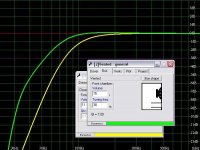
Our measurements would be quite different. Mine were done for this specific design application, mounted in the box, with the tweeter baffle suspended above. The measurements were taken on the listening axis, at tweeter level, which puts them about at a point 60º off the driver's axis and 4" or so above the drivers center. The driver will obviously roll off much sooner and break ups will be down in spl level due to the off axis natue of the listening and/or mic position. Mine are also on a pretty small baffle of only 7" wide. These would make them quite different than standard on axis measurements and probably explains most of the differences you see. Here is the raw measurement of the woofer at 1 meter, tweeter height as describe above, taken in SoundEasy. I do not have the impulse response graphs saved.
I will contact Paul about further details on the TL model. He uses M.J. Kings Mathcad worksheets.
Our measurements would be quite different. Mine were done for this specific design application, mounted in the box, with the tweeter baffle suspended above. The measurements were taken on the listening axis, at tweeter level, which puts them about at a point 60º off the driver's axis and 4" or so above the drivers center. The driver will obviously roll off much sooner and break ups will be down in spl level due to the off axis natue of the listening and/or mic position. Mine are also on a pretty small baffle of only 7" wide. These would make them quite different than standard on axis measurements and probably explains most of the differences you see. Here is the raw measurement of the woofer at 1 meter, tweeter height as describe above, taken in SoundEasy. I do not have the impulse response graphs saved.
A simple two-way design for the W5-704 and a tweeter (both available from PE) is at:
http://madspeaker.com/extras/704CROSS.PDF
The design allows for transient coherence (time alignment) on a flat baffle and accurate overall reproduction.
Mark
http://madspeaker.com/extras/704CROSS.PDF
The design allows for transient coherence (time alignment) on a flat baffle and accurate overall reproduction.
Mark
MarkMcK said:
A simple two-way design for the W5-704 and a tweeter (both available from PE) is at:
http://madspeaker.com/extras/704CROSS.PDF
The design allows for transient coherence (time alignment) on a flat baffle and accurate overall reproduction.
Mark
Hi,
Not wanting to be pendantic but your article states far field but gives no
baffle dimensions - which are of critical for BSC and the ripple it causes.
/sreten.Markmck, Thanks for posting your mods. I noticed most of your damping is done at the outer edge of the cone. Is this where most breakups occur?
I ask because I puzzlecoated a Tang-Band W4-616 paper driver but now the sound lacks dynamics and is over-damped. I need to use less Puzzlecoat to hit just the worst breakups. So should I:
1) Just run a ring of Puzzlecoat around the outer edge of the cone?
2) Do 4 radial stripes in an "X" pattern and leave the rest of the cone bare paper?
3) Thin the Puzzlecoat more like 3 parts water / 1 Puzzlecoat instead of 1 part water / 3 Puzzlecoat?
w4-616
- Status
- This old topic is closed. If you want to reopen this topic, contact a moderator using the "Report Post" button.
- Home
- Loudspeakers
- Multi-Way
- Design Review: Tang Bang W5-704s Woofer