Thanks Ra7,
To be honest I am not very happy, It sounds more correct, more like a wall with all frecuencies there, but not sure, something missing, like it sucked life? sorry, not sure about how to describe it in technical terms since I am not sure what is going on. Could be too many things, so the only option is keep experimenting.
1) I am presumming that maybe I just like highs higher, so I can fell all the micro detail and bronzes, even if it's not flat...
2) other posibility is that I am equalizing too aggresively, since I am applying tons of dB EQ here and there. So I want to review all I have done and see If I can apply less EQ. I am thinking that maybe, move from a 10W amp to a 100W amp for the woofer may put the woofer beside the horn, so there will be less necesity to attenuate the horn. Also want to do as much attenuation as possible in analog.... I felt like, maybe, dynamics suffered a bit... but I am only GUESSING at this point. more work to do...
3) Pending is the work with the woofer, and it's crossover point is now at 500hz. This horn/driver is suppoused to go far lower so I expect to be measuring again and doing some comparisons.
4) I think I need to think and listen a lot about what is going on here...
A flat response doesn't mean it sounds good. It can be it is flat because there is a phase difference and the sum is good but further a way from the loudspeaker it isn't that flat any more.
Measure a meter for the speaker, and measure it on the listening position about 3 or 4 meter from the loudspeaker. And see where a drop or raise in the response is.
Your response seems to raise about 5dB from the mid section up, for what I have experienced it comes very close the level from low to mid and the level of the tweeter to the rest. you need to tune it very precise. Measure edit and listen until it sounds good.
To measure the low mid to high response you use a small time window of about 5 msec with low smoothing or no smoothing to see all details of the measurement.
Last edited:
Here's some reading you can do before taking the next measurements:
Crossover mods for the AR4x - Mods, Tweaks, and Upgrades to the Classics - The Classic Speaker Pages Discussion Forums
In the thread above, David Smith, who is a well regarded speaker designer, goes through a new crossover design for an old speaker. Pay close attention to the phase overlap that he talks about. Helmuth above also mentioned it. It is very important that the phase of the two drivers overlap in the crossover region.
Phase is nothing but the arrival time of frequencies relative to one another. For crossover design, the only thing that matters is the phase of one driver in relation to the other. In that linked thread, Dave shows how you can get that using Holm. Here's a quick summary of the procedure:
1. In the device and signal tab, check the box that keeps in/out stream active. This will keep time.
2. In data analysis tab, choose Causal impulse.
3. Make measurement of tweeter or woofer. Keep position of mic fixed for entire process. I like to position the mic at the vertical midpoint of the woofer and the horn. That way the vertical lobe will be symmetrical about the mic axis.
4. Then in data analysis tab, use the time locked feature. Click Use. This will lock the time at the previous measurement. The next measurement will be in relation to the previous measurement. This means, you will get correct phase relationship between drivers.
5. Measure next driver.
Now you can see the phase of the two drivers in relation to one another. When you start putting in the crossover, or every time you make a change to any driver, you will need to repeat the entire process again, because filter changes phase. When you are done, amplitude must sum to flat, and phase must overlap through the crossover, atleast until the individual drivers' outputs are down about 25-30db. This will give a smooth transition from one driver to the other.
Last edited:
Going back to pages 23 and 24, there was some speculation on how low the BMS mid range could go. The long answer seems to also be 300hz.
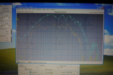
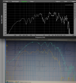
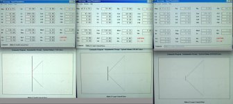
Here is a screen shot of two different horns with the BMS 4592 on them. One is a DDS horn, about 22"x22" in size. The other is a much larger horn, about 48" x 33", and about 5' long. (56cm x 56cm, and 122cm x 84cm x 153cm) The smaller horn is limited by its size, but the much larger horn shows the lower limits of the mid driver. Which is right at 300hz.
I am not sure why of the differences in sensitivity. I am wondering if it is mostly distance. As in, the larger horn, the mic is over one meter further from the driver. I would think that the volume would start dropping as the distance gets further from the horn mouth, not from the driver mouth. There is also the possibility that something else such as amp volume changed from one test to the other.
Attachments
Hi Jack,
On my end I´ve been listening to my system with 300hz and 6.3khz croosever poitnts with BW18db/oct filters.
I am mating this with a 18inch woofer Eminence Omega 18a pro in a U-Frame (open baffle).
I am using three amps. Solid state for Woofers.
I think the horn sounds great: guitars, voices and up sound natural and alive.
I have lack of live and like a hole (that is hard to measure but I can listen to it) in the mid-low range, like Toms in a drum set. I am guessing it's Woofer behavior and Bass Integration.
I think the solution for this needs a 15in Woofer to have mids that perform better.
Some friend was suggesting a Sealed box with a Linkwitz transform.
Also some times I feel some distorsions, but my 2360A have some cavities inside where the fiber glass colapsed in the joint of the two sections of the horn, the damage is very noticeable when you look at it, and I guess it has to produce some damage to the sound. That is why this week I plan to fix those imperfections with some kind of epoxy, and then I am also painting the horns with a "wine" color.
Going back to woofers, I don´t want to have more than 1 woofer, so the only option I see is going active. What do you think about a sealed box? Any suggestions for drivers? I was looking at the internet at JBL and TAD. Tad is too expensive. I am thinking if a JBL 15in woofer could to a fine work here. or maybe more modern drivers?
Regarding equalization, I discovered that too many filters kind of break the sound and suck life. So now I am just applying only one EQ filter with a smile shape to raise the extremes. Even when this didn't solve everything, I think result was much better.
Best
I was looking at the internet at JBL and TAD. Tad is too expensive. I am thinking if a JBL 15in woofer could to a fine work here. or maybe more modern drivers?
My thoughts are buy anything but a vintage JBL. There are so many speaker companies that offer better things than you can get from JBL. (All of their good speakers go into systems, not sold as components.) I can never believe how much my used JBL speakers go for on eBay. I get more than I paid for them 20 years ago, used. And now used much more. A new speaker from any other company will be a better purchase. If you get something cheap, it will not have the added cost of paying for the three letter logo, and if you buy something that costs as much as a JBL, you will get better quality.
I was owing some pictures. Here there are a few shots from the weekend:
An externally hosted image should be here but it was not working when we last tested it.
An externally hosted image should be here but it was not working when we last tested it.
An externally hosted image should be here but it was not working when we last tested it.
An externally hosted image should be here but it was not working when we last tested it.
The inverse distance drop starts at the driver diaphragm itself and continues throughout the horn.Going back to pages 23 and 24, there was some speculation on how low the BMS mid range could go. The long answer seems to also be 300hz.
Here is a screen shot of two different horns with the BMS 4592 on them. One is a DDS horn, about 22"x22" in size. The other is a much larger horn, about 48" x 33", and about 5' long. (56cm x 56cm, and 122cm x 84cm x 153cm) The smaller horn is limited by its size, but the much larger horn shows the lower limits of the mid driver. Which is right at 300hz.
I am not sure why of the differences in sensitivity. I am wondering if it is mostly distance. As in, the larger horn, the mic is over one meter further from the driver. I would think that the volume would start dropping as the distance gets further from the horn mouth, not from the driver mouth. There is also the possibility that something else such as amp volume changed from one test to the other.
If you took measurements 1/2 meter and at the horn mouth, then inside the horn you will notice SPL will continue to increase at roughly 6 dB each halving of distance.
Horn low frequency cut off and sensitivity is a function of flare rate and other design features, I'd expect the 4592 could go lower than 300 Hz on some horns.
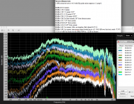
As an example, the response of an EVDH1AMT (3" diaphragm driver) on a 22.5" x 11.25" x (approximately) 17" deep horn is shown.
In spite of being a fraction of the size of either of the horns you tested, the LF cut off of this horn (a WS Paraline) is much lower, around 200 Hz compared to 300 and 500 Hz for your larger horns.
Art
Attachments
The inverse distance drop starts at the driver diaphragm itself and continues throughout the horn.
If you took measurements 1/2 meter and at the horn mouth, then inside the horn you will notice SPL will continue to increase at roughly 6 dB each halving of distance.
Art
This is wonderfully wacky for me. I had no reason to consider it before yesterday.
The reason its so fun, is that the spectrum is continually changing through out the horn. Not only is the SPL changing, but the makeup of that SPL. Because the lower frequencies will take longer, (more horn) to impedance couple, there will be less of the lower frequencies closer to the throat of the horn, and then, as the lower frequencies grow in SPL as they couple, the higher frequencies are already dropping in SPL.
So, does a frequency that has not been coupled yet, and therefore not reached its higher SPL from horn loading, still drop in inverse distance? I would think it would have to. So it would be getting quieter, and then louder.
Am I interpreting this all correctly?
Jack,This is wonderfully wacky for me. I had no reason to consider it before yesterday.
The reason its so fun, is that the spectrum is continually changing through out the horn. Not only is the SPL changing, but the makeup of that SPL. Because the lower frequencies will take longer, (more horn) to impedance couple, there will be less of the lower frequencies closer to the throat of the horn, and then, as the lower frequencies grow in SPL as they couple, the higher frequencies are already dropping in SPL.
So, does a frequency that has not been coupled yet, and therefore not reached its higher SPL from horn loading, still drop in inverse distance? I would think it would have to. So it would be getting quieter, and then louder.
Am I interpreting this all correctly?
For me to opine on what you are interpreting I'd have to see measurements of what you are interpreting
") .
.I have only tested "inside" of one horn, my conical 13 x 13 degree Maltese horn.
http://www.diyaudio.com/forums/multi-way/212240-high-frequency-compression-driver-evaluation.html
My inverse distance test on that horn shows more LF the closer to the throat measured, which seems opposite of what you are writing.
Also, there is a "bubble" of sound surrounding the mouth of a horn, within which the inverse distance law does not work as expected, while within the horn it appears to work normally again.
Art
Attachments
Jack,
My inverse distance test on that horn shows more LF the closer to the throat measured, which seems opposite of what you are writing.
Art
This is the opposite of what I am writing. And also goes against an interpretation of what I have seen Tom write. In specific, he was asked about LF interfering with the HF driver, and the diaphragm of it. He wrote that it was not an issue, as the LF was band passed out of the program by the time it was at the throat of the horn. This is a different scenario though. As the "LF" in question is coming from the driver itself, and not another driver mounted further down the horn.
Horn low frequency cut off and sensitivity is a function of flare rate and other design features, I'd expect the 4592 could go lower than 300 Hz on some horns.
Art
I would also expect the 4592 to go lower, but isn't this the optimal horn for such an experiment?
Isn't a long horn better for LF propagation than a short one with a large mouth that opens up very fast?
The horn again, is straight sides, with a 2" throat, and 5' deep, with a 48" x 33" mouth. I am measuring about 1' outside the mouth.
Jack,I would also expect the 4592 to go lower, but isn't this the optimal horn for such an experiment?
Isn't a long horn better for LF propagation than a short one with a large mouth that opens up very fast?
The horn again, is straight sides, with a 2" throat, and 5' deep, with a 48" x 33" mouth. I am measuring about 1' outside the mouth.
If all four sides are "straight sided" the horn has a conical expansion.
Counter intuitive (to me), a one foot long conical horn has the same cutoff as a 5 foot conical horn.
Earl Geddes (repeatedly) pointed this out to me recently, until I actually ran some simulations myself, I had a hard time believing it, and admitting I was wrong in stating otherwise.
Pattern control does extend lower with a larger conical horn, but the LF corner is not extended.
The conical Synergy horns "cheat" the LF corner with multiple drivers tapping in to different points of a conical horn, allowing a lower cut off than the sidewall angles would otherwise indicate.
A rapidly flaring exponential horn can go lower in a much smaller package than a conical horn, but will not have constant directivity as a conical horn does.
Jack,
If all four sides are "straight sided" the horn has a conical expansion.
Counter intuitive (to me), a one foot long conical horn has the same cutoff as a 5 foot conical horn.
Earl Geddes (repeatedly) pointed this out to me recently, until I actually ran some simulations myself, I had a hard time believing it, and admitting I was wrong in stating otherwise.
Pattern control does extend lower with a larger conical horn, but the LF corner is not extended.
The conical Synergy horns "cheat" the LF corner with multiple drivers tapping in to different points of a conical horn, allowing a lower cut off than the sidewall angles would otherwise indicate.
A rapidly flaring exponential horn can go lower in a much smaller package than a conical horn, but will not have constant directivity as a conical horn does.
You have now blown my mind twice in one day.
Essentially I have a horn with pattern control to 125hz, but LF propagation to 300hz.
Counter intuitive (to me), a one foot long conical horn has the same cutoff as a 5 foot conical horn.
Earl Geddes (repeatedly) pointed this out to me recently, until I actually ran some simulations myself, I had a hard time believing it, and admitting I was wrong in stating otherwise.
Hi Art,
How are you defining cutoff?
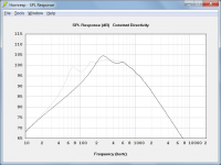
The attached screenprint compares the power responses of two conical horns:
Horn 1
S1 = 350
S2 = 20000
L12 = 150
Fta = 24.78
Horn 2
S1 = 350
S2 = 1871.03
L12 = 30
Fta = 24.78
The horn axial lengths are different but the throat areas and conical flare tangent angles are the same. It seems to me that the longer horn (light-grey SPL trace) has the better bass extension, and therefore a lower 'cutoff'.
Kind regards,
David
Attachments
With a 33" height, probably more like -6 dB pattern control to 410 Hz.You have now blown my mind twice in one day.
Essentially I have a horn with pattern control to 125hz, but LF propagation to 300hz.
You'll have to measure it to tell for sure.
Sounds like a monster, who made it?
David,Hi Art,
How are you defining cutoff?
The attached screenprint compares the power responses of two conical horns:
Horn 1
S1 = 350
S2 = 20000
L12 = 150
Fta = 24.78
Horn 2
S1 = 350
S2 = 1871.03
L12 = 30
Fta = 24.78
The horn axial lengths are different but the throat areas and conical flare tangent angles are the same. It seems to me that the longer horn (light-grey SPL trace) has the better bass extension, and therefore a lower 'cutoff'.
I define cutoff as the corner point where the low frequency response of a horn starts to rapidly drop.
Earl Geddes wrote in post #5974 of this thread:
http://www.diyaudio.com/forums/multi-way/103872-geddes-waveguides-599.html
"I objected to the statement (made by weltersys in post 5966) "A larger diameter round conical horn with more mouth area has a lower cutoff frequency than a smaller horn." It was incorrect when it was stated and its still incorrect. I don't understand why everyone keeps wanting to change the discussion - maybe to avoid having to admit that this statement is wrong?"
After doing some sims in Hornresp to prove my statement correct, found I was wrong, and posted my retraction in Post #5984.
Not able to find published T.S. parameters for any compression drivers, used a familiar driver found to be useful in horn mid designs, the Eminence Alpha 6, which has a lower Fs (and far more Xmax) than the BMS 4590 or 4592 being discussed here, or the B&C HF drivers Earl tends to use.
I had used a very small VRC (compression chamber volume) volume which restricts driver excursion and LF output, but causes a rising response above cutoff. With the small back chamber, changing horn size (with sidewall angle the same) makes virtually no difference.
Today I tried increasing the VRC from .4 liter to 1.4 liter to allow the driver to reach it's 3.5mm Xmax at 100 watts, which lowers the cutoff frequency by around an octave.
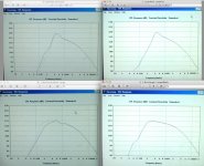
The upper SPL charts show the .4 VRC, (perhaps similar to the small compression chambers used by most mid/high compression drivers) the lower show the 1.9 rear chamber volume optimized for the Alpha 6.
The enormous differences in the horn size required for minimal changes in the LF cutoff are rather striking.
The "small" horn at 15 cm deep(about 6 inches) LF corner is 112 dB at 265 Hz, F3 of 109 dB is at 210 Hz.
Quadrupling the length, and with 38 times the volume, the "large" horn results in a LF corner of 113 dB at 190 Hz, F3 of 110 dB is at 152 Hz, a bit over one third octave lower response than the "small" horn.
The "larger" horn is truly a monster with a mouth of 99999 square centimeters, (107 square feet) the largest input available in Hornresp. This mouth size was still not large enough to maintain the 45.1 angle used by the other horns with 180 cm (5.9 feet) of length.
Even so, it had a higher LF corner than the large horn, with 115 dB at 230 Hz, F3 of 112 dB at 180 Hz, less than 1/3 octave lower than the small horn, although it occupies 856 times the volume.
Perhaps you can explain why your examples results are so different than mine, and explain to Earl Geddes why he's wrong
. Art
Attachments
Last edited:
Hi Art,
Thanks for the comprehensive response, and for explaining what you mean by the cutoff of a conical horn.
I sought your clarification on this matter because strictly speaking, a conical horn does not have a theoretical cutoff frequency in the same way that an exponential horn does.
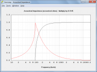
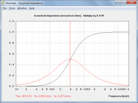
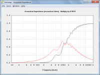
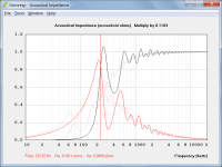
This can be illustrated by comparing the throat acoustical impedance of an infinite exponential horn (attachment 1) to that of an infinite conical horn (attachment 2).
The throat resistance of an infinite exponential horn is zero below a cutoff frequency given by fc = m * c / (4 * Pi) where m = ln (S2 /S1) / L12. For frequencies lower than fc, no power is transmitted down the horn, and the impedance at all positions along the path is purely reactive. For the example given in attachment 1, the cutoff frequency is 100 Hz.
Traditionally a conical horn has been considered not to have a specific cutoff frequency, but I notice that the new Beranek & Mellow 'Acoustics' book published in 2012 defines the cutoff frequency of an infinite conical horn as fc = c / (2 * Pi * x1) where x1 is the distance from the cone apex to the horn throat. This is the frequency at which the throat acoustical resistance equals the throat acoustical reactance. For the example given in attachment 2, the cutoff frequency becomes 391 Hz.
The reason why our results are different can best be seen by examining at the throat acoustical impedances of the various horns.
Attachment 3 compares your 'small' and 'larger' horns. Notice how the results are quite similar.
Attachment 4 compares the two finite conical horns I used as examples in my previous post. Notice how the results vary considerably, even though the theoretical cutoff points (as defined by Beranek and Mellow) are the same for both horns.
Earl is correct in that theoretical cutoff frequencies are influenced by horn flare rate rather than horn length or mouth area. However, the practical power response cutoff can be significantly affected by horn length and mouth size, as demonstrated in my previous post.
In my view, therefore, you are both correct - based on your different interpretations of cutoff.
Kind regards,
David
I define cutoff as the corner point where the low frequency response of a horn starts to rapidly drop.
Thanks for the comprehensive response, and for explaining what you mean by the cutoff of a conical horn.
I sought your clarification on this matter because strictly speaking, a conical horn does not have a theoretical cutoff frequency in the same way that an exponential horn does.
This can be illustrated by comparing the throat acoustical impedance of an infinite exponential horn (attachment 1) to that of an infinite conical horn (attachment 2).
The throat resistance of an infinite exponential horn is zero below a cutoff frequency given by fc = m * c / (4 * Pi) where m = ln (S2 /S1) / L12. For frequencies lower than fc, no power is transmitted down the horn, and the impedance at all positions along the path is purely reactive. For the example given in attachment 1, the cutoff frequency is 100 Hz.
Traditionally a conical horn has been considered not to have a specific cutoff frequency, but I notice that the new Beranek & Mellow 'Acoustics' book published in 2012 defines the cutoff frequency of an infinite conical horn as fc = c / (2 * Pi * x1) where x1 is the distance from the cone apex to the horn throat. This is the frequency at which the throat acoustical resistance equals the throat acoustical reactance. For the example given in attachment 2, the cutoff frequency becomes 391 Hz.
Perhaps you can explain why your examples results are so different than mine, and explain to Earl Geddes why he's wrong
The reason why our results are different can best be seen by examining at the throat acoustical impedances of the various horns.
Attachment 3 compares your 'small' and 'larger' horns. Notice how the results are quite similar.
Attachment 4 compares the two finite conical horns I used as examples in my previous post. Notice how the results vary considerably, even though the theoretical cutoff points (as defined by Beranek and Mellow) are the same for both horns.
Earl is correct in that theoretical cutoff frequencies are influenced by horn flare rate rather than horn length or mouth area. However, the practical power response cutoff can be significantly affected by horn length and mouth size, as demonstrated in my previous post.
In my view, therefore, you are both correct - based on your different interpretations of cutoff
.Kind regards,
David
Attachments
- Status
- This old topic is closed. If you want to reopen this topic, contact a moderator using the "Report Post" button.
- Home
- Loudspeakers
- Multi-Way
- Design: Horn High Sensitivity Speakers