It's good to have Jim McShane's expert input. In some circles, he's known as "Mr. Citation". ") He's also a go to guy for tubes and some parts, like the sockets this project needs.
He's also a go to guy for tubes and some parts, like the sockets this project needs.
FWIW, I was thinking of Russian 6П3С-E (6p3s-e) O/P tubes, initially and KT66s as a later refinement.
I'd forgotten about the 6CL6, which allows the H/K parts values to be used. Like the 12BY7, the 6CL6 is out of production, but the available supply is not under the sort of pressure the 12BY7 supply is. The 6922 I call for in the alternative voltage amplifier block is in production and draws only 300 mA. of heater current, but you must regulate its B+. "Name your poison."
Speaking of heater current, the worst case scenario of a 6CL6, an ECC99, and 2X KT66s draws 4.05 A., which just over what 1 of the 4 A. filament windings in the AnTek toroid is rated for. I don't think that will be a problem, especially when the 2nd 4 A. winding is loafing, while energizing a low current draw voltage multiplier. No additional magnetics have to be purchased.
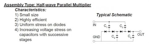
Multi-stage voltage multipliers are not difficult to construct. I'm uploading a schematic "swiped" from VMI that's highly illustrative. The graphic is for a positive PSU and we're dealing in negative voltages. So, stand everything on its head. Tapping a multiplier in different places should (IMO) be self evident.
He's also a go to guy for tubes and some parts, like the sockets this project needs.FWIW, I was thinking of Russian 6П3С-E (6p3s-e) O/P tubes, initially and KT66s as a later refinement.
I'd forgotten about the 6CL6, which allows the H/K parts values to be used. Like the 12BY7, the 6CL6 is out of production, but the available supply is not under the sort of pressure the 12BY7 supply is. The 6922 I call for in the alternative voltage amplifier block is in production and draws only 300 mA. of heater current, but you must regulate its B+. "Name your poison."
Speaking of heater current, the worst case scenario of a 6CL6, an ECC99, and 2X KT66s draws 4.05 A., which just over what 1 of the 4 A. filament windings in the AnTek toroid is rated for. I don't think that will be a problem, especially when the 2nd 4 A. winding is loafing, while energizing a low current draw voltage multiplier. No additional magnetics have to be purchased.
Multi-stage voltage multipliers are not difficult to construct. I'm uploading a schematic "swiped" from VMI that's highly illustrative. The graphic is for a positive PSU and we're dealing in negative voltages. So, stand everything on its head. Tapping a multiplier in different places should (IMO) be self evident.
Attachments
guys way too tech.
dumb this down a bit
is there a reason the kt66 were mentioned over kt88?
also in my ss builds always like to go overbuild of power supplies
as in 625va or 800va toroid
why just 200va for these?
sorry but i really don't know
on another note
today i was reading anything i could find about tube use and came across a writeup on triode, pentode and ul versions how they were thought of in the audio world.
i went back and looked at pictures i took of the cary. it had a switch on it labeled triode and ul. not knowing anything i switched back and forth and did't seem any much different.
so i left them in the triode setting that it came.
now for the first time i think i found out why the cary acted low powered.
a idiot was using it... me
damn i feel stupid
no freakin wonder it had no power only 20watts in triode.
i lost $1800 on this
it's 40 watts only in ul
i sold a perfectly fine rocket 88 for $600
the silver lining here is for the first time i see this new build will rock
i'm so sorry to all of you who tried to tell me
Last edited:
is there a reason the kt66 were mentioned over kt88?
The KT66, like the 7581 and the 6p3s-e, is a member of the 6L6 family and mates perfectly with the Hammond 1650P O/P transformer. Simply shoving a more capable tube in a socket that was not designed for it DOES NOT make for better performance. AAMOF, things rate to "go south" rather quickly.
A historical note, the 6L6 beam power tetrode was introduced by RCA back in the 1930s. 6L6 family tubes have been in continuous production, someplace, since then. All hail the longevity champion.
Eli, I'm wondering if the 59T choke you were recommending was based on a single PS or on monoblocks. The reason I mention it is because if it was based on a single PS then it might be a good idea to split the PS AFTER the mains transformer and use independent independent rectifiers, chokes and caps for each channel. A choke with more than 2.5 henrys is definitely possible in that situation since they'll be carrying less current.
If that choke recommendation is already considered in each channel's current level, well, never mind.
If that choke recommendation is already considered in each channel's current level, well, never mind.
Member HollowState was kind enough to provide a very clear Cit. 5 schematic on a single page. That scan becomes part of this thread.
thanks Eli and Victor....
Eli, I'm wondering if the 59T choke you were recommending was based on a single PS or on monoblocks.
From the beginning, the OP stated a desire for monoblocks. I'm planning on a massive, as in total overkill, 300 mA. or so B+ rail in each of the 2 chassis. The amount of cojones available will be very substantial.
Transient behavior will be outstanding.I'd like the OP/builder to find the $ to buy a pair of Modern Maida regulator PCBs, from 1 of our valued members. Regulated g2 B+ is a key element in maximizing open loop linearity, when full pentode mode "finals" are employed, as is the case in the Cit. 5.
The Cit. 5 is an excellent amp, but H/K did cut a few corners. We'll try to rectify those "errors", along with taking advantage of some "modern" advances.
Hi Eli, how would you rate the irons in the HK cit.5 compared to say the Dynaco's or the Marantz? and are they available still as an off the shelf item?
The "iron" in the Cit. 5 is definitely better than Dynaco's. However, it's not as good as the stuff H/K used in the Cit. 2, which many think is the best ever. The Hammond 1650P transformers selected for this project are not as good as the H/K originals, but (thankfully) Mullard style circuitry is not "touchy", the way Williamson style is, about O/P "iron" and the O/P, with his 35 Hz. high pass filtration setup, rates to do very well, indeed. Get the o'scope out and fine tune the phase compensation.
AFAIK, Cit. 5 O/P transformers are not available, "off the shelf". However, the skilled winders around may be able to "clone" them. Maybe member Bandersnatch has the info.
thanks Eli, i do hope Bandersnatch chimes in....
in the RCA tube manual 50 watt amp, United Transformer Corp.LS6L4 was specified, have been hunting down data for this opt with no luck, perhaps you can shed more info?
Here you go...
An externally hosted image should be here but it was not working when we last tested it.
So you are going to reverse engineer one... that would probably require some secret handshake, good luck with your quest!
i already have a pair made, at 15lbs each, my build is close....
Cool, how do they measure on the bench?i already have a pair made, at 15lbs each, my build is close....
Cool, how do they measure on the bench?
i have not come to that yet, they are meant for another tube, will post them once done....
Member HollowState was kind enough to provide a very clear Cit. 5 schematic on a single page. That scan becomes part of this thread.
thank you to all who cared enough to progress this into a build state.
eli the lastest schematic
is it to be built exactly as that drawing shows?
thank you to all who cared enough to progress this into a build state.
eli the lastest schematic
is it to be built exactly as that drawing shows?
No. I will address only 1 channel. Everything I say applies to the corresponding parts in the other channel.
You will choose between the 6CL6 and the parts values H/K used with the 12BY7 or you will you will use the 6922 cascode alternative I previously uploaded.
The 6CG7 will be replaced by the higher gm ECC99. The value of R11 and R13 will change to a value that's TBD. R10 gets replaced by a 10M45S CCS and, instead of being grounded, it's connected to a low voltage negative supply, to guaranty adequate "breathing room".
Remember what I said about some corners being cut. The O/P tube biasing arrangement is one of those places. You will build with an individual bias set trim pot. for each O/P tube. Each O/P tube's cathode will "stand" on a 1% tolerance 10 Ω resistor. You measure the voltage drop across the resistor, with a DMM, and use Ohm's Law to compute the "idle" current. Individual trim pots. provide the greatest flexibility and you will not need to buy a panel meter/switch.
Simply RC decoupling O/P tube g2 B+ from the plate B+ was common enough, back in the day. Please, please, buy the Maida regulator PCBs, as regulated g2 B+ is "heads and shoulders" better than RC decoupling. One of Jim McShane's tweaks, when rebuilding a Cit. 5, is to add a choke to the g2 B+ supply. A choke is good, but outright regulation is even better.
Use 1% tolerance resistors in the NFB loop, to ensure the 2 channels match. C6 is a phase compensation part. It's value depends on the specific O/P transformer employed. The proper value for that part is determined, empirically, by injecting square waves into the amp and observing the shape of the O/P waveform, with an oscilloscope. If you don't have an o'scope, speak up now and I'll provide a brute force method of phase compensation.
Give me a few days to put a "hen scratch" schematic of the PSU together. When I post that, I hope to have some additional items for you.
In the meantime get your "iron" orders in and filled. Have you decided on what the 2X chassis will be? You said monoblocks, from the very outset, and that's what is being targeted. Allow plenty of room. Don't skimp on space and have a failed project. "Shoehorning" parts in is a prescription for big trouble.
thanks eli
you are one in a million
and yes mono block for looks first and piece of mind second as in each with it's psu.
looks are number 1 to me as in sit in my chair and see manly built floorstander 3 ways with a mono block amps sitting at the base of each. all equipment on racks to the side out of view.
nothing looking forward but the business end.
no panic now as a clear vision is in the works. i have ordered the 2 antec , hammonds 1650p and chokes, the ceramic sockets , cardas rca's and cardas binding posts
i have 2 virtual dynamics power 3 power cords for these.
today i got a sheet of 1/8 aluminum to build chassis .
chassis are my most loved project. i have a idea for 2 of the most stunning bouncing around
just to keep interest's in this build black walnut pictures to follow as work starts when all parts arrive.
you know the underside photo's of people builds they have these terminal strip things.
what are they called ? tried to find them but must be searching wrong name.
Last edited:
- Status
- This old topic is closed. If you want to reopen this topic, contact a moderator using the "Report Post" button.
- Home
- Amplifiers
- Tubes / Valves
- design advise