Hello again
So this amp hasn't been working for a while now and I just haven't had time to look at it. I ran it all day at work with zero issues but accidentally got left on overnight, when I came in the next day the fuse was blown and the amplifier obviously won't turn on.
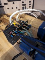
I recently got settled into my new house after moving late last year and had some time to dig into it again. I checked all the solder joints and re-did a couple things like adding speaker terminals and new interconnect wires that are more flexible. I've cleaned the PCB and tried some other tubes I had but it does the same thing every time, immediately blows the fuse.
I'm not exactly sure what happened or where I should start, any tips are appreciated!
So this amp hasn't been working for a while now and I just haven't had time to look at it. I ran it all day at work with zero issues but accidentally got left on overnight, when I came in the next day the fuse was blown and the amplifier obviously won't turn on.
I recently got settled into my new house after moving late last year and had some time to dig into it again. I checked all the solder joints and re-did a couple things like adding speaker terminals and new interconnect wires that are more flexible. I've cleaned the PCB and tried some other tubes I had but it does the same thing every time, immediately blows the fuse.
I'm not exactly sure what happened or where I should start, any tips are appreciated!
Attachments
120V primary, 300V secondary x 1.414 = 424V peak.
The first capacitors are rated at 450V (424V peak going to them, with the mains at 120VAC).
Is the amplifier in an industrial area?
Power mains voltage spikes?
127VAC power mains takes the first capacitor all the way to 450V.
Check the diodes, and the first B+ filter capacitor, and the second B+ capacitor.

Your advice was 100% spot on.120V primary, 300V secondary x 1.414 = 424V peak.
The first capacitors are rated at 450V (424V peak going to them, with the mains at 120VAC).
Is the amplifier in an industrial area?
Power mains voltage spikes?
127VAC power mains takes the first capacitor all the way to 450V.
Check the diodes, and the first B+ filter capacitor, and the second B+ capacitor.
I got around to going over the amp this morning and found both diodes and one of the B+ caps were bad. I swapped out those parts and it fired right up.
It definitely has a bit of hum but that could be due to the janky layout I have going on the moment.
I appreciate the help.
There are a couple of ways you can go about it. You can either add in a cap and choke on the input, moving the rectifiers off the board or you can splice in a choke and resistor to replace the first resistor. I found that if I changed the rectification to tube rectification changing the first resistor to a choke cancelled out the voltage drop on the rectifier. There's more than one way to do this, it's kinda up to you.
That's a little bit beyond me, at least at first glance. I'll need to read up on this a bit more so I have a better understanding before I go changing anything.
I'm fairly novice at this stuff. I build stuff from kits that usually come with instructions, I get lost pretty quickly when deviating. I appreciate the suggestions though, I'm going to look into it!
I'm fairly novice at this stuff. I build stuff from kits that usually come with instructions, I get lost pretty quickly when deviating. I appreciate the suggestions though, I'm going to look into it!
- Home
- Amplifiers
- Tubes / Valves
- Decware ZKIT-1 help needed