Hi guys
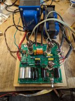
So a few years ago I picked up a pair of Decware ZKIT-1 2 channel amp kits that I got about 80% finished before sitting on a shelf for the next 3 years. I have some time off work and decided that I wanted to try and finish them.
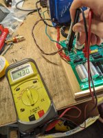
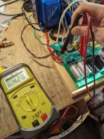
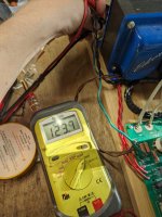
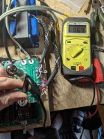
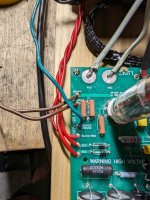
I have one amp fully assembled and wired in a state good enough to test. Unfortunately it does not turn on, the tubes do not light up. I've checked all my component values and all seems correct. The manual lists a few points to measure, points A and B both measure 430VDC, they're supposed to be 346V and 309V. The other points all measure zero. I have very little circuit troubleshooting knowledge and I'm sure I've missed something dumb, so I'm trying to learn.
I have attached the circuit diagram and my measurements. Any help is very appreciated.
So a few years ago I picked up a pair of Decware ZKIT-1 2 channel amp kits that I got about 80% finished before sitting on a shelf for the next 3 years. I have some time off work and decided that I wanted to try and finish them.
I have one amp fully assembled and wired in a state good enough to test. Unfortunately it does not turn on, the tubes do not light up. I've checked all my component values and all seems correct. The manual lists a few points to measure, points A and B both measure 430VDC, they're supposed to be 346V and 309V. The other points all measure zero. I have very little circuit troubleshooting knowledge and I'm sure I've missed something dumb, so I'm trying to learn.
I have attached the circuit diagram and my measurements. Any help is very appreciated.
Attachments
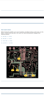
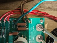
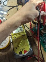
First carefully check between the ends of the primary winding, BLACK and BLACK, when powered up.
Should measure 120VAC there. If so, then the primary wiring, switch, and fuse are ok.
If not, check all these parts and the related wiring.
Then if you do have 120VAC input, and still none of the tubes light up, look for a bad connection at the ends
of the filament winding wires, BRN and BRN. There should be 6VAC between these ends.
Last edited:

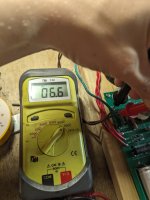
Don't look, measure the filament winding ends BRN/BRN for 6VAC.
Trust but verify. Bear in mind that voltage can be present at the wire end,
but not at the pcb trace it is connected to, due to a "cold" solder joint.
Then if that is ok, check at each tube socket for 6VAC between pins 4 and 5.
First guess for the problem is the right filament wire solder joint.
Trust but verify. Bear in mind that voltage can be present at the wire end,
but not at the pcb trace it is connected to, due to a "cold" solder joint.
Then if that is ok, check at each tube socket for 6VAC between pins 4 and 5.
First guess for the problem is the right filament wire solder joint.
Last edited:
Ok, then the tubes must be lighting up, even if you can't see it. Do they feel warm at all?
Turn out the lights to better see if they light up. Some tubes sorta hide their filament, though.
The excessive high voltage means the tubes are not drawing the proper amounts of current.
Next measure the DC voltage "V" across the 150 ohm 5W output stage bias resistor.
The total output stage current (for both tubes) is equal to ( V / 150 ) amps.
If you measured 15VDC, the current would be 100mA total for both tubes.
Last edited:
All 3 tubes show no signs of life, all feel cold and even with the lights off I don't see anything. Usually tubes don't light up the brightest but these are definitely not lighting up.
I don't measure any DC voltage across that resistor
I don't measure any DC voltage across that resistor
Attachments
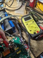
Ok, it seems that the filament circuit is the problem.
Turn off the power, remove the 6N1P input tube, turn the power back on,
and measure for 6VAC on top of the socket at pins 4 and 5 (read numbers clockwise on top).
If there is 6VAC present on top of the socket, next measure the 6N1P input tube out of its socket,
for some resistance between pins 4 and 5.
Last edited:
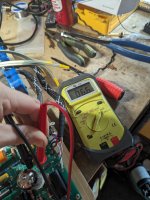
Ok, make sure it's the correct cathode pin #3 for each.
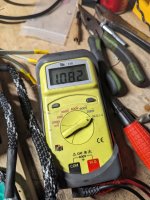
Do you verify left pin #3 to ground is still 1.08k?
Right 0.15 k ohms is the correct reading.
Left is wrong 1.08k instead of correct 0.15k (150 ohms).
Make sure the left reading is measured from pin 3 to ground.
If left reading is still 1.08k, check all wiring and soldering for the left EL-84 tube socket.
Look for solder shorting two places on the board where it shouldn't.
Also verify all left channel output tube related parts are installed in the right places.
Last edited:

Ok good, that would have been impossible.
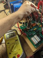
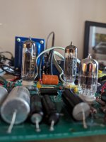
Now with all tubes on board, apply power.
We will make some high voltage measurements.
Attach the black probe to ground.
Make a list of all DC voltages using the red probe on each EL84 socket pin. Skip pins 4 and 5.
Then do the same for the 6N1P. Skip pins 4 and 5.
Now with all tubes on board, apply power.
We will make some high voltage measurements.
Attach the black probe to ground.
Make a list of all DC voltages using the red probe on each EL84 socket pin. Skip pins 4 and 5.
Then do the same for the 6N1P. Skip pins 4 and 5.
So the other output transformer primary lead is red/black, not blue as in the schematic?
And it has 0VDC?
It's odd that you can measure point A at 430VDC, but not either of the red leads, since they are connected together.
Make sure you are on DC volts range on the meter, not on AC volts. Please confirm this before we go on further.
Also it's odd that the input tube has plate voltage but conducts no current, like the filament is off.
Maybe there are more than just one problem with the board.
Last edited:
- Home
- Amplifiers
- Tubes / Valves
- Decware ZKIT-1 help needed