Nad 245bee gives max power output with only 0.27v of input. I would like to increase this to about 1.1v. (The same as my Nad 216)
I have basic knowledge and tools to solder and I assume this is possible to do somehow using a resistor, but don't know exactly how.
Anyone with knowledge that want to enlighten me?
I have basic knowledge and tools to solder and I assume this is possible to do somehow using a resistor, but don't know exactly how.
Anyone with knowledge that want to enlighten me?
Seems as a rather low threshold
Are you Shure? that the NAD isn't damaged ?
It actually is in the data sheet:
Input sensitivity 270mV (ref. rated power)
Voltage gain 35dB
The problem is that I get to much static hiss because of this.
We would need to see a circuit diagram to advise on modifying the unit.
If you can't come up with one then the safest option is simply to add an attenuator to each input. That can be done externally or possibly internally if the layout suits a bit of diy work.
I actually have the service manual. Used it for adjusting the idle current that was way to low.
Attachments
Hmmm.
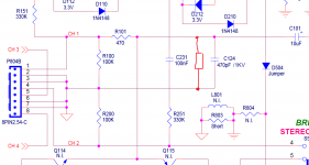
Seeing the full circuit and I would advise against altering anything within the power amp itself (possible stability problems), however it may be possible to add an attenuator.
Look at the diagram. You would have to do this on all four channels. Its only an idea but it looks feasible...
1/ R101 would need increasing from 470 ohm to say 4k7.
2/ You would add a new resistor across C124.
That would form a divider network for that channels input. The new resistor would be chosen to give the desired attenuation. For example the additional 4k7 across the cap would then divide the signal by two. You could go as low as needed in value for that resistor to reduce the level applied to the amp.
The input impedance would be lowered by doing this but any solid state preamp would easily drive the attenuator.
Attachments
Yes, but alter the second 4k7 to suit.
A bit more time now... so plugging some numbers in we get:
0.27 volts (we assume that is an rms voltage) gives full output which I think is around 50 or so watts rms for that amp.
So put another way 0.27 volts gives around 20 volts rms at the output. Overall voltage gain is 20log(V1/V2) which is 37db. So that is in the right ballpark for your quoted 35 db gain.
You want full output for around 1.1 volts (again assume rms values).
So using common resistor values suggests a 4k7 and a 1k8 resistor. That will reduce your 1.1 volts rms to around 300 mv rms.
Pure Curiosity.. only:
What inputs is that Amp designed for then, to utilize that level ?
I don't know, this is strange I think?. Its a normal 4 channel amplifier 4x35w from Nad. Nothing special.
This down below is a copy/paste from the data sheet.
Input sensitivity 270mV (ref. rated power)
Voltage gain 35dB
35 watts. That fits then.
35 watts equals 16.7 vrms into 8 ohms. So the gain calculates at 20log (16.7/0.27) which is 35.8 db.
Okay, so its good then, but not for my application.
I used to think that every amp maxed out at about the samt voltage. I my mind this means that a amp that have lets say 1 000w would need much more input then any preamp can generate to max out.
But I do realize there is something here that I don't understad.
In very basic terms, the maximum voltage an amplifier can put out is determined by the DC supply voltage it runs on. That is the maximum voltage that can be placed across the speaker and that in turn determines the maximum power available into a given load impedance.
Example.
An amplifier running on a dual -/+12 volt supply (or a single 24 volts DC rail). Assuming no losses the speaker could see plus 12 volts (cone moves out), or minus 12 volts (cone moves in) as a maximum.
So the speaker peak to peak voltage is -/+12 volts. To get an rms voltage we take just the peak (so 12 volts) and divide that by root 2.
12/root 2 equals 12/1.414 which is 8.4 volts rms
Maximum power is voltage squared/load impedance. Lets assume 8 ohm load.
So (8.4*8.4)/8 equals 8.8 watts rms.
That is the maximum output possible from that amplifier running on a -/+12 volts supply into 8 ohms.
The gain of the amplifier can be any desired value we choose. We could have a gain of one (unity gain) meaning we would need to apply 8.4 volts to the input, or we might want to make the same amplifier really sensitive and get full output from just 1 millivolt. The maximum output is always the same... all that alters is how much input voltage we need to apply to achieve it.
In very basic terms, the maximum voltage an amplifier can put out is determined by the DC supply voltage it runs on. That is the maximum voltage that can be placed across the speaker and that in turn determines the maximum power available into a given load impedance.
Example.
An amplifier running on a dual -/+12 volt supply (or a single 24 volts DC rail). Assuming no losses the speaker could see plus 12 volts (cone moves out), or minus 12 volts (cone moves in) as a maximum.
So the speaker peak to peak voltage is -/+12 volts. To get an rms voltage we take just the peak (so 12 volts) and divide that by root 2.
12/root 2 equals 12/1.414 which is 8.4 volts rms
Maximum power is voltage squared/load impedance. Lets assume 8 ohm load.
So (8.4*8.4)/8 equals 8.8 watts rms.
That is the maximum output possible from that amplifier running on a -/+12 volts supply into 8 ohms.
The gain of the amplifier can be any desired value we choose. We could have a gain of one (unity gain) meaning we would need to apply 8.4 volts to the input, or we might want to make the same amplifier really sensitive and get full output from just 1 millivolt. The maximum output is always the same... all that alters is how much input voltage we need to apply to achieve it.
Yes, that much I actually do understand (belive it or not). but I don't understad why Nad (in this case) chose to have such a high gain on such a smal amp with low power and obviously also low voltage output. Instead of adapt the gain so that every amp in there lineup from 35w to 150w (or whatever) would put out it's max voltage output at the samt voltage input.
Hi,
Original amplifier circuit may have been designed for an integrated amp with all gain in the power amp (no active electronics prior power amp).
I'd just put a potentiometer (~10k) in front and adjust gain that way.
Okay, a potentiometer in serial whit the signal or between signal and ground?
Okay, a potentiometer in serial whit the signal or between signal and ground?
Connected as potentiometer where signal enters one end, signal ground the other end and viper connects to your NAD input.
Yes, that much I actually do understand (belive it or not). but I don't understad why Nad (in this case) chose to have such a high gain on such a smal amp with low power and obviously also low voltage output. Instead of adapt the gain so that every amp in there lineup from 35w to 150w (or whatever) would put out it's max voltage output at the samt voltage input.
Often a chosen amplifier topology works best within a certain gain range. If you look at data sheets for most of the common chip amps you will see they specify a minimum gain it is to be used at. Go below that and the thing becomes totally unstable. Same for discrete designs.
I would guess NAD got the levels correct for partnering with their recommended preamp.
Using a pot would need a four gang part to adjust the input to all four channels simultaneously.
Connected as potentiometer where signal enters one end, signal ground the other end and viper connects to your NAD input.
Okay, I get it. Seems like the easiest solution.
Often a chosen amplifier topology works best within a certain gain range. If you look at data sheets for most of the common chip amps you will see they specify a minimum gain it is to be used at. Go below that and the thing becomes totally unstable. Same for discrete designs.
I would guess NAD got the levels correct for partnering with their recommended preamp.
Using a pot would need a four gang part to adjust the input to all four channels simultaneously.
Yes that is probably why Nad did what they did, to match something else.
And I use the amp in bridge mode so I will only need a stereo potentiometer.
- Status
- This old topic is closed. If you want to reopen this topic, contact a moderator using the "Report Post" button.
- Home
- Source & Line
- Analogue Source
- Decreasing gain on Nad 245bee