One question: If i want to check the audio drive board outside from the amp:
I have two laboratory power suplys here, can i use one for the 12VDC to connect to the board, and the other one with 5VDC to the board, or did i need two supplys for the 5v wich means +5V, -5V and the ground together to A-Grnd?
And for the high side can i use the 9V Battery parallel to all caps at the same time or must it one by one?
I think so its easier to compare all drive signals.
I have only the driver board here at work, and i will be back home an week about.
Also i expect, that is more easy, to see if i have a small failure on the driver board. So i can compare all signals and see small differences without the main board interferring.
At the moment it was, that three banks getting hot, one not. So i can compare this signals.
Also i expect, that is more easy, to see if i have a small failure on the driver board. So i can compare all signals and see small differences without the main board interferring.
At the moment it was, that three banks getting hot, one not. So i can compare this signals.
Hello, i want to order some spare Resistors for the Audio Driver Board. In the Tutorial are shown, which one often burned. What is the Size code for them? Iam not sure which one to order. There are to many different.
I can buy a set Formtype 1206
Cost only 50$ with series E12
I can buy a set Formtype 1206
Cost only 50$ with series E12
Last edited:
So, thanks to Mario Restucci, i got a new driver board for this amp.. The old card was to much damaged for further use.
I Mounted the board, checked everything. All ok. Signals are there without mosfets. Mounted one fet per bank, and used a low power supply.. On one bank, one high side fet gets hot, and the lamp for positive rail starts lightning a little bit. Signal is ok on this fet.
Twisted the inductors, nothing change. If i remove this bank, the lamp is off...
I expected, that both lamp will glow with a damaged inductor or something..
Does anybody has an advice?
Have you checked all the gate resistors?
Have you checked all the pulldown resistors?
Have you checked all VS resistors?
Have you checked all the big white resistors (47ohm 7-10w)?
Sometimes it is also necessary to check all the blue capacitors.
When you have checked all these components, keep in mind that even if you read a relatively correct value and in tolerance, it does not necessarily mean that each resistor is perfectly functional.
Many times (too many) for my negligence I have thrown away new mosfets, new IR21844S, new diodes, new resistors and a lot of time and effort (and money above all) when it would have been enough to change everything (even if apparently it seemed ok).
Then of course, yes, you could have a damaged inductor (in an invisible place and way) but you can only know this by taking them apart and measuring them with a special tool.
I'll give you an example: A 33ohm gate resistor, at the sight it was perfect, measuring it had a value of 33.1ohm, the other twins, were in the range of 32.4 and 32.8ohm, I thought everything was ok and I installed the new components, well, I would have liked don't do that, that resistor had to be changed, because it caused the breakage of 6 new mosfets and all 4 IRS21844s.
damn!
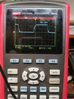
So i have this amplitude on two banks. Its the low side.. The opening voltage is interessting. The end of the amplitude is from the missing output filter. I mounted the filter back in place, then it is better. But begining of the amplitude is the same... What can cause this?
I will try with other mosfets...
I will try with other mosfets...
Honestly, I don't understand much, are you doing low voltage procedures without inductors?
To me that waveform is pretty normal on the gate (during normal class D operation).
I usually do this (after I am sure that all my resistors are really ok) I install the driverboard I check if all the low sides are there, then with an auxiliary 12v battery (even 1A is fine) I check if they are all there too the high sides.
When I did this test, I am 95% certain that by installing only 1 fet per bank for each stage, everything will be fine (my tests are all with the battery voltage at about 11.1v and with low rail voltage, after all, if i really checked all resistors, it will work, then i switch to high rail voltage, if it still works, i increase the battery voltage).
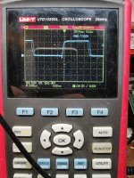
No, on this amp i work with a low voltage supply at the rail, because this amp has some tricky problems. The Amplitude at this bank is not ok, because the fet gets hot. If i check the amplitude on another bank, the signal is straight, without any interuption.. The gate resistors and pulldown resistors are new, and checked three times.. I dont know, what can cause this.. I will add a picture from the other bank.
Attachments
Very strange!
Which mosfets are you using? It seems that IRS21844 struggles to drive that mosfet, are all the same mosfets you are using right now? are they all good? If you are using IRFP064N, try using the mosfets you would definitely use (something like IRFP360LC or FDA24N40 or IRFP460LC or FDA24N50 or FQA24N50).
Ah, important, take a picture of the driverboard and tell me which IR21844 is causing the problem.
Last edited:
So, it seems, that i kept an old set of mosfets, maybe from China.. Those 360LC are ok,, but they cant be driven in a good way.. I used now FDA24N40f, from where i know, that they came from mouser... Now everything is ok, drive perfect, each mosfet stay cold..
I think i will use the 24N40 in this amp,they have the same paramter, and a little less gate charge.
I think i will use the 24N40 in this amp,they have the same paramter, and a little less gate charge.
- Status
- This old topic is closed. If you want to reopen this topic, contact a moderator using the "Report Post" button.
- Home
- General Interest
- Car Audio
- DD Z1a damaged