Konnichiwa,
You don't absolutely have to have 2.2uF. I use that value as I recommend it as minimum coupling cap for the S&B TX-102 which i use as passive linestage (and recommend).
Look here:
[url]http://www.angela.com/catalog/capacitors/Angela_SBE_SCR.html
[/URL]
Yes, they are really NanoFarad.
Okay, they are not exactly cheap, but if purchased from the usual industrial sources they are a lot cheaper than most "audiophile" capacitors. If you must save money make the 10nF Capacitors 160V Polystyrene Types (not that they come out much cheaper).
No. You may not even use them as coupling capacitors.
Actually, you may use whatever you like, but if the result is mediocre or barely adquate don't blame me, okay?
I tend to use generic Nippon Chemi Con (VX) series axial and/or radial capacitors. They are very cheap and also used by Sakuma San. They work out fine if you don't want to stretch for motor run MKP's.
I would be carefull with bypassing. If you must, 1uF of fairly high esr capacitors seems indicated. That means MKT over MKP etc....
Sayonara
Kofi Annan said:I haven't been able to find anyone that sells Audyns in the US and the VAT plus shipping overseas makes these a bit cost prohibitive. Anyone know where I can find Audyns in the US or that can recommend a reasonably suitable substitute for the 2.2uF coupling cap (not Mundorfs-- too expensive)?
You don't absolutely have to have 2.2uF. I use that value as I recommend it as minimum coupling cap for the S&B TX-102 which i use as passive linestage (and recommend).
Look here:
[url]http://www.angela.com/catalog/capacitors/Angela_SBE_SCR.html
[/URL]
Kofi Annan said:Also, Kuei recommended silver / mica for the 10n and 1n (are these really in nanofarads?) caps in the circuit.
Yes, they are really NanoFarad.
Kofi Annan said:Again, these are a bit expensive, so are there any other that would make a good substitute?
Okay, they are not exactly cheap, but if purchased from the usual industrial sources they are a lot cheaper than most "audiophile" capacitors. If you must save money make the 10nF Capacitors 160V Polystyrene Types (not that they come out much cheaper).
Kofi Annan said:Maybe metallized poly film (MKSE / PPMF)?
No. You may not even use them as coupling capacitors.
Actually, you may use whatever you like, but if the result is mediocre or barely adquate don't blame me, okay?
Kofi Annan said:I'm planning in using JJ electrolytics in the PSU since they seem to have the best bang / buck ratio. Are there any other 47uF / 500V electrolytics you'd recommend in their place that are in the $8.00 range?
I tend to use generic Nippon Chemi Con (VX) series axial and/or radial capacitors. They are very cheap and also used by Sakuma San. They work out fine if you don't want to stretch for motor run MKP's.
Kofi Annan said:Also, if I bypassed the electrolytics, what values would I use?
I would be carefull with bypassing. If you must, 1uF of fairly high esr capacitors seems indicated. That means MKT over MKP etc....
Sayonara
Thanks!
I broke down and decided to go wth the silver mica. Also went with the 1.5uF Angela tin foil. Hopefully that will do.
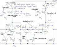
At the risk of exposing myself to be the schmuck that I am, I have attached the RIAA circuit in question and listed the parts I intend to use.
As this is a learning experience for me, I'd like to get some feedback on whether these selections will work together or if they will make me wretch uncontrollably for months. If the case is the latter, please recommend some replacements and ridicule me accordingly.
Thanks,
Kofi
I broke down and decided to go wth the silver mica. Also went with the 1.5uF Angela tin foil. Hopefully that will do.
At the risk of exposing myself to be the schmuck that I am, I have attached the RIAA circuit in question and listed the parts I intend to use.
As this is a learning experience for me, I'd like to get some feedback on whether these selections will work together or if they will make me wretch uncontrollably for months. If the case is the latter, please recommend some replacements and ridicule me accordingly.
Thanks,
Kofi
Attachments
Hi,
Koffi,
May I ask whether you plan on using this phonostage as a standalone unit to drive an amplifier directly?
If so, you may want to add a cathode follower to the output or use a different topology for the second stage in order to reduce the output impedance. It is a tad on the high side....
As for the components you chose, nothing wrong with it per se although I'm no fan of Solen polyprops at all, would it not be wiser to use ordinary components for the first built?
Sorry if I missed some obvious things here...I haven't followed the entire thread.
Cheers,")
Koffi,
May I ask whether you plan on using this phonostage as a standalone unit to drive an amplifier directly?
If so, you may want to add a cathode follower to the output or use a different topology for the second stage in order to reduce the output impedance. It is a tad on the high side....
As for the components you chose, nothing wrong with it per se although I'm no fan of Solen polyprops at all, would it not be wiser to use ordinary components for the first built?
Sorry if I missed some obvious things here...I haven't followed the entire thread.
Cheers,
May I ask whether you plan on using this phonostage as a standalone unit to drive an amplifier directly?
You may. The next stage will be a line amplifier, then 2A3 SET monoblocks.
As for the components you chose, nothing wrong with it per se although I'm no fan of Solen polyprops at all, would it not be wiser to use ordinary components for the first built?
Yes it would, only I'm not smart enough to separate the merely ordinary parts from the total doody. If there are some less expensive components you'd recommend that don't outright stink, I'd love to hear it. I'm only going with the parts that I saw recommended in this long, long post.
Long.
This has already been a learning experience and I certainly don't want to get ahead of myself by getting in over my head with components I don't need. Its hard for a newbie like me to determine which parts are worth going medium / high quality on and which can be upgraded later.
Please let me know your (collective) thoughts on this and thanks very much for responding!
Kofi
Konnichiwa,
It will.
I don't see anything that is prejudicial to performance. But one or two notes.
Modern Holco's have no longer got any advantages over other RC55 standard resistors, sonically but are still sold at a premium.
The gridleak resistor and output resistor (10M & 1M respectively) do not require particulary high quality resistors.
Critical for sound are the RIAA Resistors, the cartridge load, the first stage cathode resistor and the Anode loads, in that sequence of impact.
Try making the gridstopper carbon composition, that is more important than the value.
The +B Dropper resistors are relatively uncritical.
I would recommend for all uncritical positions generic metal films of sufficient power rating from Mouser.
Mills on the Anode load of the 2nd stage is fine. For the first stage I think a premium grade low noise (Vishay? Caddock?) Resistor is indicated, the same might also be a good choice for the EQ.
Well, the output impedance is around 3K, not exactly low, but with 1nF cable capacitance (which is well past what I'd recommend - stick to low capacitance cables) the -3db point is still 50KHz.
I'd leave the cathode follower off if good sound is desired.
Sayonara
Kofi Annan said:I broke down and decided to go wth the silver mica. Also went with the 1.5uF Angela tin foil. Hopefully that will do.
It will.
Kofi Annan said:As this is a learning experience for me, I'd like to get some feedback on whether these selections will work together or if they will make me wretch uncontrollably for months. If the case is the latter, please recommend some replacements and ridicule me accordingly.
I don't see anything that is prejudicial to performance. But one or two notes.
Modern Holco's have no longer got any advantages over other RC55 standard resistors, sonically but are still sold at a premium.
The gridleak resistor and output resistor (10M & 1M respectively) do not require particulary high quality resistors.
Critical for sound are the RIAA Resistors, the cartridge load, the first stage cathode resistor and the Anode loads, in that sequence of impact.
Try making the gridstopper carbon composition, that is more important than the value.
The +B Dropper resistors are relatively uncritical.
I would recommend for all uncritical positions generic metal films of sufficient power rating from Mouser.
Mills on the Anode load of the 2nd stage is fine. For the first stage I think a premium grade low noise (Vishay? Caddock?) Resistor is indicated, the same might also be a good choice for the EQ.
fdegrove said:May I ask whether you plan on using this phonostage as a standalone unit to drive an amplifier directly?
If so, you may want to add a cathode follower to the output or use a different topology for the second stage in order to reduce the output impedance. It is a tad on the high side....
Well, the output impedance is around 3K, not exactly low, but with 1nF cable capacitance (which is well past what I'd recommend - stick to low capacitance cables) the -3db point is still 50KHz.
I'd leave the cathode follower off if good sound is desired.
Sayonara
Thanks again for the advice!
Being eager to concoct an appropriate parts list, I have again modified my list of parts for the project. Being new, I probably blew it.
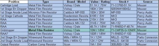
I swapped the Holcos for Vishay / Dales, but I don't really know if I'm any better off. I added a Caddock power resistor for the 1st stange anode load and I'm trying Roederstein Resista resistors for the cathode and an RIAA resistor position.
I had to try different makes since there are certain values of resistance by manufacturer that are either not carried or not available.
Anyway, if you would, please take a look at the attached .jpg of my current working parts list. I simply cannot find a 10M carbon comp resistor from my regular sources, so I went with metal film. If this will cause the UN building to explode when I turn it on, please let me know.
Also, are the Watt ratings OK for these?
Then after this, can you take a look at the rash on my leg?
OK, skip that. Just the parts list will do nicely.
Thanks so much for putting up with this. As a thank you, I have a few leftover "oil for food" dollars I can funnel your way, if you get my drift.
Kofi
Being eager to concoct an appropriate parts list, I have again modified my list of parts for the project. Being new, I probably blew it.
I swapped the Holcos for Vishay / Dales, but I don't really know if I'm any better off. I added a Caddock power resistor for the 1st stange anode load and I'm trying Roederstein Resista resistors for the cathode and an RIAA resistor position.
I had to try different makes since there are certain values of resistance by manufacturer that are either not carried or not available.
Anyway, if you would, please take a look at the attached .jpg of my current working parts list. I simply cannot find a 10M carbon comp resistor from my regular sources, so I went with metal film. If this will cause the UN building to explode when I turn it on, please let me know.
Also, are the Watt ratings OK for these?
Then after this, can you take a look at the rash on my leg?
OK, skip that. Just the parts list will do nicely.
Thanks so much for putting up with this. As a thank you, I have a few leftover "oil for food" dollars I can funnel your way, if you get my drift.
Kofi
Attachments
Hi,
I see some 12W, even 30W resistor on your list.....
I pinched myself in the arm but no, I am not dreaming.
Surely that must be a mistake? I can't see any reason to pick such high wattage resistors for anode loads in a simple phono pre where there's just a couple of miliamps flowing??
I noticed you have some Roederstein Resistas on your list.
These are great resistors, I love them, but I would not use them as cathode/anode resistors even though they'd probably work just fine.
Instead, if you want to keep your budget tight, I'd recommend as gridleak and for the RIAA correction.
For the anode/cathode resistor Dale (1W) RCN55 and similar should be O.K.
The gridstopper on the ECC88 is probably not even needed as it has the entire RIAA correction on it's grid already but it won't hurt either.
If you want a "no holds barred" version then I'd recommend the nude Vishay bulkfoils (if you can find them) for the RIAA section and cartridge loading and anything else directly in the signal path.
Keep in mind that some (actually most) MM cartridges require some capacitive loading on top of the one provided by the cable capacitance of the phono leads. If so, then that cap (50 to 150pF) is best put across the cartridge load resistor (51K?) and of the best quality you can find, silvered mica, polystyrene or polypropylene would be good.
For the 10M gridleak bias resistor I'd opt for a metalfilm type. I'm not sure how noisy or not these carbon comp resistors are but I've used Resistas in that position with good results in the past, so...
Anyway, I'll leave TL to fill in the blanks as he should be the more familiar with the circuit....
Cheers,
P.S. Should you have a calibrated capacitance meter then you can put it to good use to hand select the RIAA caps so you can match values for both channels.
Konnichiwa,
The 12W are okay and actually suggested for the 12K. The second stage is run "low & hot" to minimise anode impedance.
Not really. The second stage anode resistor dissipates around 3 Watt.
Experience shows that the ECC88 likes to oscillate. Depending how tight the circuit is wired it will do that within this circuit.
Me too.
Sayonara
fdegrove said:I see some 12W, even 30W resistor on your list.....
The 12W are okay and actually suggested for the 12K. The second stage is run "low & hot" to minimise anode impedance.
fdegrove said:For the anode/cathode resistor Dale (1W) RCN55 and similar should be O.K.
Not really. The second stage anode resistor dissipates around 3 Watt.
fdegrove said:The gridstopper on the ECC88 is probably not even needed as it has the entire RIAA correction on it's grid already but it won't hurt either.
Experience shows that the ECC88 likes to oscillate. Depending how tight the circuit is wired it will do that within this circuit.
fdegrove said:For the 10M gridleak bias resistor I'd opt for a metalfilm type.
Me too.
Sayonara
Konnichiwa,
A few notes. The Gridstopper is the 100R, NOT the 10M. The 10M is the gridleak resistor and the circuit is gridleak biased.
Power rating, all resistors are fine as 0.5W excepting the Anode Load and +B dropper resistor for the Output Stage. They needs to be 3W & 9W minimum, the Mills is probably overkill for +B Dropper and you could try one of the various TO-220 cased power film resistors (Caddock, Meggit, Vishay come to mind).
Sayonara
Kofi Annan said:Anyway, if you would, please take a look at the attached .jpg of my current working parts list. I simply cannot find a 10M carbon comp resistor from my regular sources, so I went with metal film. If this will cause the UN building to explode when I turn it on, please let me know.
A few notes. The Gridstopper is the 100R, NOT the 10M. The 10M is the gridleak resistor and the circuit is gridleak biased.
Power rating, all resistors are fine as 0.5W excepting the Anode Load and +B dropper resistor for the Output Stage. They needs to be 3W & 9W minimum, the Mills is probably overkill for +B Dropper and you could try one of the various TO-220 cased power film resistors (Caddock, Meggit, Vishay come to mind).
Sayonara
I currently have 6W for the 12K output stage anode load and 2W for the 1K B+ dropper, I'd better get a big 1K!
I recently fired up the circuit using a silicon rectifier PS with CLCRCRCRC.
There is simply no hum and hiss is very low, this is one quiet design.
I'm letting silver micas develop but initial impressions are very favourable.
I recently fired up the circuit using a silicon rectifier PS with CLCRCRCRC.
There is simply no hum and hiss is very low, this is one quiet design.
I'm letting silver micas develop but initial impressions are very favourable.
Konnichiwa,
You will be okay with these, they will merely be running a litle warmer than I like. Using 300% expected dissipation rating keeps the resistors running cool.
Sayonara
clivetjm said:I currently have 6W for the 12K output stage anode load and 2W for the 1K B+ dropper, I'd better get a big 1K!
You will be okay with these, they will merely be running a litle warmer than I like. Using 300% expected dissipation rating keeps the resistors running cool.
Sayonara
I see some 12W, even 30W resistor on your list.....
Surely that must be a mistake? I can't see any reason to pick such high wattage resistors for anode loads in a simple phono pre where there's just a couple of miliamps flowing??
Actually, that's nothing. I was originally going to use a 1977 Lincoln Continental Mark V as the B+ dropper resistor (7.5 x10^238 W dissipation) and The Bay City Rollers as the second stage anode load resistor.
See, in the U.S. we think big.
BIG
OK... maybe too big.
The 12W are okay and actually suggested for the 12K. The second stage is run "low & hot" to minimise anode impedance.
As aforementioned, I like big, so this is good.
For the 10M gridleak bias resistor I'd opt for a metalfilm type.
So noted.
Actually, I'm kidding about the "big" thing. I like small and cheap. Like Mrs. Annan. She's small and cheap.
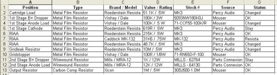
I changed the parts list to remove some of the ridiculous values (see attached), and I think I'll probably start with these and make changes as time goes on.
This is going to be a real learning experience for me, so I'll likely have more questions as parts arrive and I begin to think about the layout.
Take a look at my final parts list and let me know if I will be committing audio atrocities. Note that I could not find certain values in the recommended resistors, so I did the best I could.
Also, I can't thank you (collectively)** enough. I know you are stooping pretty low to help a nimrod like me and I really appreciate it.
Kofi
**[You know, I really wish we had a collective "you" in English as many other languages have. We have "youze" (Brooklyn), "youze guys" (Northern Brooklyn) and "y'all" (Alabama), but no grammatically accepted version.]
Attachments
Hi,
Looks O.K. except for the anode load resistor of the ECC83, the 100K should be 3W. (Check with Mouser, they should carry it)
"We" appreciate the thought............
Cheers,
Take a look at my final parts list and let me know if I will be committing audio atrocities. Note that I could not find certain values in the recommended resistors, so I did the best I could.
Looks O.K. except for the anode load resistor of the ECC83, the 100K should be 3W. (Check with Mouser, they should carry it)
**[You know, I really wish we had a collective "you" in English as many other languages have.
"We" appreciate the thought............
Cheers,
Konnichiwa,
Looks good, except there is absolututely no need for the 3W/180K, it can be 1/2". The ECC83 runs at 0.6mA. The 100K Resistor dissipates 0.036W and the 180K 0.065W.
I'd probably use standard (Mouser CCF55 Range) metal Films for all but ECC83 cathode, cartridge load, gridstopper & RIAA and of course the big resistors for the output stage. Mrs Annan should like the change in cost.
Sayonara
Kofi Annan said:I changed the parts list to remove some of the ridiculous values (see attached), and I think I'll probably start with these and make changes as time goes on.
Looks good, except there is absolututely no need for the 3W/180K, it can be 1/2". The ECC83 runs at 0.6mA. The 100K Resistor dissipates 0.036W and the 180K 0.065W.
I'd probably use standard (Mouser CCF55 Range) metal Films for all but ECC83 cathode, cartridge load, gridstopper & RIAA and of course the big resistors for the output stage. Mrs Annan should like the change in cost.
Sayonara
Thanks again for all the great advice!
I've opted for Resistas (did Snoop Dogg name these?) for the RIAA, even though I'll have to add a 30K1 and a 1K5 to get the 31K6 value.
Kuei-- I've read your post (#60 on this topic) about star grounding and I want to clarify.
I'll have two ground lugs, one for each stage. The grounds of each stage will connect to their respective lugs, but then the each ground lug will be connected together, right?
Any other assembly advice you could give would be appreciated. I plan to use the PSU that Yagoolar proposed (this is almost the same as Kuei's)-- a CRCRCRCRC for the B+ and a regulated supply (LM317) for the filaments. I'll be using a dual mono supply for the B+ but only one for the filaments.
Thanks so much for helping an average schmuck.
Kofi
kuei Yang Wang,
Can I remove the RIAA network in your ecc83/ecc88 circuit and drop in a S&B 10k RIAA Can? What mods would be needed? A series 10K after the ecc83 to satisfy the 10k and keep the grid resistor on the ecc88 same?
Can I parallel triodes in the ecc88 for more gain and lower ouput impedance?
Joe
Can I remove the RIAA network in your ecc83/ecc88 circuit and drop in a S&B 10k RIAA Can? What mods would be needed? A series 10K after the ecc83 to satisfy the 10k and keep the grid resistor on the ecc88 same?
Can I parallel triodes in the ecc88 for more gain and lower ouput impedance?
Joe
Hi,
More gain? More gain?
First of all paralleling triodes does not change the gain.
Secondly, how much gain do you think you need?
A passive RIAA stage such as the one used here has, on average,
an insertion loss of about 20 dB.
For a linelevel preamp you don't even need any gain so 3dB is a handful already.
If you'd simply remove the RIAA correction you'd probably end up with a gain of about 60dB....That's a lot of noise in anyone's book, won't you think?
Cheers,
Can I parallel triodes in the ecc88 for more gain and lower ouput impedance?
More gain? More gain?
First of all paralleling triodes does not change the gain.
Secondly, how much gain do you think you need?
A passive RIAA stage such as the one used here has, on average,
an insertion loss of about 20 dB.
For a linelevel preamp you don't even need any gain so 3dB is a handful already.
If you'd simply remove the RIAA correction you'd probably end up with a gain of about 60dB....That's a lot of noise in anyone's book, won't you think?
Cheers,
fdegrove said:Hi,
More gain? More gain?
First of all paralleling triodes does not change the gain.
Secondly, how much gain do you think you need?
A passive RIAA stage such as the one used here has, on average,
an insertion loss of about 20 dB.
For a linelevel preamp you don't even need any gain so 3dB is a handful already.
If you'd simply remove the RIAA correction you'd probably end up with a gain of about 60dB....That's a lot of noise in anyone's book, won't you think?
Cheers,
Frank,
Sorry if it wasn't too clear, I just wanted to replace the "RIAA COMPONENTS" (the part between the 2 tubes) and replace it with the S&B "canned 10K RIAA" to still be a phono stage. I am not sure on the exact insertion loss of the 10k S&B.
Using TUBE CAD ...doesn't paralleling triode increase gain? Any drawback in sound quality?
Joe
joe3rp said:doesn't paralleling triode increase gain?
NO.
Let's say we have a single triode, and increase the voltage at the grid by 1V, and the current through the valve increases by 10mA. Hence we have a transconductance of 10mA/V.
So if we parallel two identical valves, and increase the voltage at the grid by 1V, the current through the valves will increase by 20mA (each valve increases by 10mA). This is a transconductance of 20mA/V - thus paralleling two valves doubles transconductance.
Amplification factor, m is a constant (okay, it varies a little with operating point, but not tremendously unless you have a very non-linear valve), and describes the maximum voltage gain attainable from the valve (i.e. with a very large Rl, or with a constant current load).
Anode resistance is the ratio of amplification factor to transconductance (ra=m/gm), so the anode resistance halves, and as such the output impedance from the stage will decrease by a factor of roughly two.
Hi,
I see....Yeah I did completely misunderstand what it was you wanted to do, sorry.
The S&B RIAA is an LCR correction I presume?
With the 10K I'd use a cathode follower to isolate it from the first tube.
Try to find some implementations for similar LCR corrections, they were originally 600 Ohm and xformer coupled between stages.
Ishido designed some phono stages around similar units. I think TL experimented with these as well, not sure.
Either way, this isn't exactly easy peasy stuff to get right though...
10K makes it easier but still.
Cheers,
Sorry if it wasn't too clear, I just wanted to replace the "RIAA COMPONENTS" (the part between the 2 tubes) and replace it with the S&B "canned 10K RIAA" to still be a phono stage. I am not sure on the exact insertion loss of the 10k S&B.
I see....Yeah I did completely misunderstand what it was you wanted to do, sorry.
The S&B RIAA is an LCR correction I presume?
With the 10K I'd use a cathode follower to isolate it from the first tube.
Try to find some implementations for similar LCR corrections, they were originally 600 Ohm and xformer coupled between stages.
Ishido designed some phono stages around similar units. I think TL experimented with these as well, not sure.
Either way, this isn't exactly easy peasy stuff to get right though...
10K makes it easier but still.
Cheers,
- Home
- Source & Line
- Analogue Source
- DC phono