What do you expect, when the panels of the prototype enclosure in this case are most certainly vibrating / flexing?
Didn't he write he already reenforced the enclosure several times? The enclosure has to flex by several Millimeters in every direction on every enclosure wall to dampen the resonator that much - if the simulation is correct.
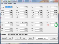
You are obviously not familiar with how Hornresp operates, which makes me wonder just how qualified you are to pass judgement on its performance.
The last time I simulated multiple drivers in hornresp, you had to change the parameters yourself, there was no way to just increase the number of drivers. Since you've obviously much more proficient with hornresp, would you please kindly enlighten the readers by which of the parameters in the screenshots you've read the use of two drivers and especally, in which configuration? I mean, the impedance simulation and measurement differ by that much, I strongly assume it's a parameter or input mistake. So, you know hornresp, what is it then? You don't want to show a matching simulation to the measurements?
The last time I simulated multiple drivers in hornresp, you had to change the parameters yourself, there was no way to just increase the number of drivers.
Tools --> Driver Arrangement.
It shows up on the Input Parameters screen, e.g. Nd [2P 2S] is how it displays when you wire 4 drivers in series / parallel to maintain the same resistance as a single driver.
Mostly I just play about in hornresp, but I do sometimes RTFM - or at least skim the help file for the term I'm after.
Tractrix with phase plugs and other corrections attempts
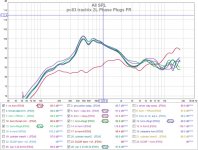
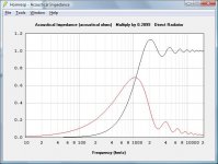
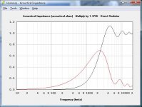
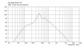
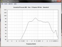
After some reading and many attempts I still can't extend the horn gain in the 2Khz to 4Khz region using throat adapters or phase plugs or other tricks. Graph #1 shows the effects of the trials, all impacts are in the higher freq range above 4Khz.
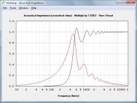
I even suspected the horn itself and replaced the pc83 full range with a dc28f tweeter to see if the horn even worked at higher freq, and it does. Graph#2 shows the gain at higher frequency, with a nasty hole @12K that I created with my adapter.
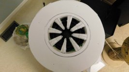
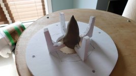
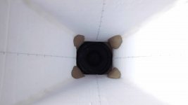
The rest are some pics of what I tried with the pc83. Still not sure why the response falls off in the 2-4Khz range. It was the same behaviour in the previous horns.
After some reading and many attempts I still can't extend the horn gain in the 2Khz to 4Khz region using throat adapters or phase plugs or other tricks. Graph #1 shows the effects of the trials, all impacts are in the higher freq range above 4Khz.
I even suspected the horn itself and replaced the pc83 full range with a dc28f tweeter to see if the horn even worked at higher freq, and it does. Graph#2 shows the gain at higher frequency, with a nasty hole @12K that I created with my adapter.
The rest are some pics of what I tried with the pc83. Still not sure why the response falls off in the 2-4Khz range. It was the same behaviour in the previous horns.
Attachments
-
 pc83 tractrix 2L Phase Plugs FR.jpg151.9 KB · Views: 349
 -
 DSCN3184r.jpg360.6 KB · Views: 119
 -
 DSCN3182r.jpg356.2 KB · Views: 110
 -
 DSCN3181r.jpg247.1 KB · Views: 98
 -
 DSCN3180r.jpg250.2 KB · Views: 328
 -
 DSCN3179r.jpg365.8 KB · Views: 325
 -
 DSCN3178r.jpg405.1 KB · Views: 329
 -
 DC28F Tractrix 2L FR.jpg132.6 KB · Views: 352
The last time I simulated multiple drivers in hornresp, you had to change the parameters yourself, there was no way to just increase the number of drivers.
The Multiple Drivers tool was added in Version 5.40 almost fifteen years ago. Hornresp is currently at Version 42.60.
Since you've obviously much more proficient with hornresp
I should hope so, given that I am the author of the program.
would you please kindly enlighten the readers by which of the parameters in the screenshots you've read the use of two drivers and especally, in which configuration?
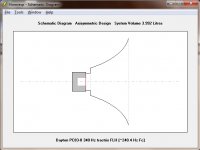
See the green-circled entry in the attached screenprint of the original design in question. "2S" means two drivers connected in series.
more tractrix phase plugs and throat plates
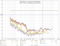
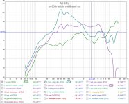
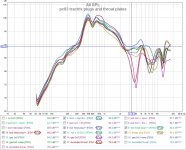
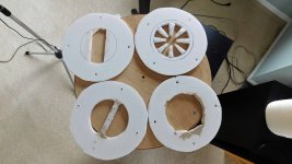
So I tried some more tricks to see if I could elevate the 2Khz-4Khz horn gain. Various throat plate adapters, and axe shaped phase plugs, and narrowing the throat. Nothing worked.
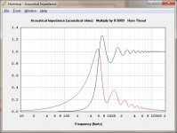
Its almost like the driver is loosing power. I did notice on the impedance curve that the inductance does not increase as expected. In fact it rises so slowly the REW cannot extract T/S parameters. It might be from the driver shorting ring (cap) to help at higher frequencies. Still not sure because I haven't fixed it yet.
Pics show some things I tried. Graph #1 shows the LF is unchanged, but in the 2-4Khz there is never an improvement.
So I threw in the towel and took what I had and EQ'd flat then LP'd the midband as best I could could as seen in Graph#2 (purple line). As a side benefit the midband distortion is lower (-60db from 400-2Khz) with a horn.
So I tried some more tricks to see if I could elevate the 2Khz-4Khz horn gain. Various throat plate adapters, and axe shaped phase plugs, and narrowing the throat. Nothing worked.
Its almost like the driver is loosing power. I did notice on the impedance curve that the inductance does not increase as expected. In fact it rises so slowly the REW cannot extract T/S parameters. It might be from the driver shorting ring (cap) to help at higher frequencies. Still not sure because I haven't fixed it yet.
Pics show some things I tried. Graph #1 shows the LF is unchanged, but in the 2-4Khz there is never an improvement.
So I threw in the towel and took what I had and EQ'd flat then LP'd the midband as best I could could as seen in Graph#2 (purple line). As a side benefit the midband distortion is lower (-60db from 400-2Khz) with a horn.
Attachments
-
 pc83 tractrix midband eq distortion.jpg128.9 KB · Views: 95
 -
 pc83 tractrix midband eq.jpg141.3 KB · Views: 86
 -
 pc83 tractrix plugs and throat plates.jpg152.6 KB · Views: 88
 -
 DSCN3190r.jpg503.9 KB · Views: 78
 -
 DSCN3189r.jpg262.1 KB · Views: 70
 -
 DSCN3188r.jpg273.1 KB · Views: 67
 -
 DSCN3187r.jpg378.9 KB · Views: 66
 -
 DSCN3186r.jpg262.4 KB · Views: 90
See the green-circled entry in the attached screenprint of the original design in question. "2S" means two drivers connected in series.
Interesting - it seems that the attachment was removed some time after my message was posted.
I will try again:
Attachments
The image shows standard elliptical waveguide - it looks a bit squashed by design.
The actual tuning was performed using a "G" clamp. The tricky part is determining where to position the clamp, and by how much to permanently "dent" the waveguide by tightening the clamp (the clamp is then removed). Return loss / VSWR is closely monitored while the localised dent is applied. The technique is more an art than a science, but very effective when done correctly
Thanks for the hint via the impedance matching analogy. I'm just happy it didn't involve a Smith chart or stubs.
It's why I'm seeing the behaviour in this midhorn. The tractrix horn is operating above cutoff so its acoustic impedance is constant. Compression drivers are meant to drive constant impedance and would work, except they usually don't go very low. The cone driver is meant to drive open air and its acoustic impedance changes with freq (squared?) and cone size. So the cone driver compensates for this by design. So my 3inch driver has a serious impedance change in the 1Khz-4Khz range which is where the problem is. Its why it occurs in all my horns.
I come across a paper by Dr Bruce Edgar [SB 1986, Midrange Horn] where this problem is described. He used 5-6 inch cones which push the impedance transition lower but it was still a problem. He found very few of the drivers tested were suitable and the best had a naturally rising response (less compensation?).
I added a few pics of the acoustic impedances of the horn, the pc83 and a larger 6inch driver.
Attachments
DonVK,
I think your horn provides the expected ~3 octaves of gain, but the driver simply does not have the motor strength to "power through" at higher frequencies, so you're left with EQ'ing as you've found out.
Maybe, I'm trying to think of a test for that.
I was only after 3-ish octaves [800-4000Hz] and the horn cutoff is below 800Hz. The SPL drop is in the same region as the acoustic impedance change for this 3inch cone driver. If the motor was power limited I don't think EQ would save it.
I'm just happy it didn't involve a Smith chart or stubs.
Another interesting project I worked on back in the late 1970's did in fact involve a Smith chart and stubs - to better match a 250KW shortwave transmitter via an open-wire transmission line to a large curtain array antenna. The towers at each end of the reflector curtain were 100 metres high
.Another interesting project I worked on back in the late 1970's did in fact involve a Smith chart and stubs - to better match a 250KW shortwave transmitter via an open-wire transmission line to a large curtain array antenna. The towers at each end of the reflector curtain were 100 metres high
That is a very big antenna. I'm assuming it was long range and intended to bounce off the stratosphere. You don't hear much of shortwave radio being used anymore.
I'm still thinking about those stubs for driver/horn matching. Edgar mentions it in his midhorn paper by using a driver/horn using a gap filled with a scrub pad. Hmm..
HornResp exported Akabak and run on ABEC-LEM
I was thinking of a way to add stubs or resonant chambers to the horn to try to get a better (smoother, extended) response. I need a tool to do some custom design sims. I could use ABEC-BEM but its design iterations take too long compared to HornResp.
HornResp has a way to export an akabak model. The problem (for me) is Akabak (16b) requires an older tool that requires a 32b OS or some emulation. However R&Dgroup (the makers of Akabak) also make ABEC and it has a LEM component that supports of alot of Akabak script (that I've tried so far). ABEC-LEM runs on 64b OS and is fast for trial iterations.
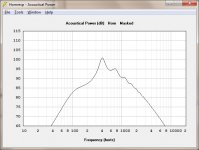
So I exported a HypEx design, fixed a couple of offending lines and ran it under ABEC-LEM. I compared the results below, and they are very good. Time to play
I was thinking of a way to add stubs or resonant chambers to the horn to try to get a better (smoother, extended) response. I need a tool to do some custom design sims. I could use ABEC-BEM but its design iterations take too long compared to HornResp.
HornResp has a way to export an akabak model. The problem (for me) is Akabak (16b) requires an older tool that requires a 32b OS or some emulation. However R&Dgroup (the makers of Akabak) also make ABEC and it has a LEM component that supports of alot of Akabak script (that I've tried so far). ABEC-LEM runs on 64b OS and is fast for trial iterations.
So I exported a HypEx design, fixed a couple of offending lines and ran it under ABEC-LEM. I compared the results below, and they are very good. Time to play
Attachments
Last edited:
That is a very big antenna. I'm assuming it was long range and intended to bounce off the stratosphere. You don't hear much of shortwave radio being used anymore.
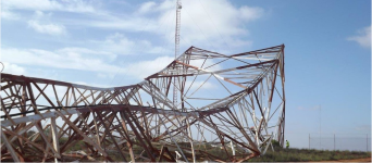
Your assumption is correct
.The curtain antenna was used to radiate Australia's international radio broadcast service 'Radio Australia' into Asia (similar to the BBC World Service and Voice of America - VOA). The station closed on 31 July 1996 and the towers were demolished in March 2017. A photo of one of the demolished towers is attached - there were actually five towers in total, supporting four curtain arrays. Satellites and the Internet have made long-range HF overseas broadcasting pretty much obsolete.
Attachments
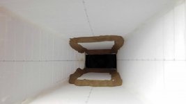
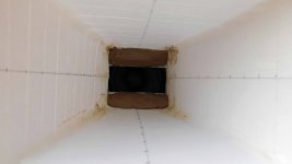
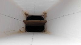
tractrix, new phase plug / front chamber
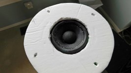
Still trying to get a usable tractrix midhorn out of this PC83. The previous ones had the typical 6db/octave drop off starting at the 500Hz peak and require EQ.
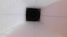
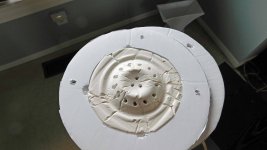
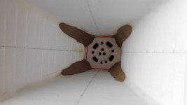
This time the front chamber volume is reduced and the throat is restricted to increase compression and velocity. The rear chamber is reduced to <0.5L by filling the cylinder with 2" polystyrene disks.
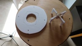
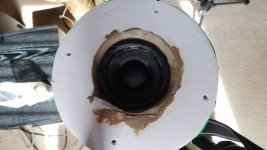
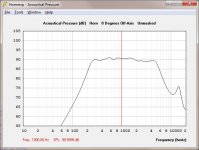
The driver cone has been replicated using a plaster of paris mold and its sitting 5mm above the driver cone. Several trial runs were made gradually increasing the hole size in the mold (restricted throat area) acting like a phase plug. I can get a reasonably flat midrange bandpass 350Hz-2KHz, or about 2.5 octaves. It's still less than the 4Khz that I was trying for, but its the best so far. FR graph is on axis, and no EQ was used.
Still trying to get a usable tractrix midhorn out of this PC83. The previous ones had the typical 6db/octave drop off starting at the 500Hz peak and require EQ.
This time the front chamber volume is reduced and the throat is restricted to increase compression and velocity. The rear chamber is reduced to <0.5L by filling the cylinder with 2" polystyrene disks.
The driver cone has been replicated using a plaster of paris mold and its sitting 5mm above the driver cone. Several trial runs were made gradually increasing the hole size in the mold (restricted throat area) acting like a phase plug. I can get a reasonably flat midrange bandpass 350Hz-2KHz, or about 2.5 octaves. It's still less than the 4Khz that I was trying for, but its the best so far. FR graph is on axis, and no EQ was used.
Attachments
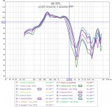
It still has that "saddle" shape in the FR like the other horns.
I wish I could increase the horn gain in 2Khz-4Khz region. Suggestions, anyone ???
Hmm, it's upper mass corner [Fhm = 2*82.14/0.78 = ~210.6 Hz] is well below the horn's intended gain BW and will be even lower after accounting for some series resistance, so wishful thinking IME.
In such cases all I can reasonably do is blend it into its HF BW and the farther away from Fs I go the less gain BW available, so to get 2-4 k would require shifting tuning an octave higher, but apparently either my simple R-O-T design routine falls apart and/or the math does because it sims basically a sharp 'one note' spike.
In short, for high gain use over a wide BW a driver with an Fs around Fc and enough motor [Qes] to push its Fhm up to where you want the horn to roll off is the goal.
Anyway, for 340 Hz I get a ~ 3 dB BSC 'step' that fills in the driver's sagging mid-range with little/no need for EQ, though with the downside of course being pitifully inefficient, but for a small room HIFI/HT app it's sufficent when one has to deal with nearby neighbors.
GM
Attachments
Thanks GM.
I had given up on this idea. I thought I needed more compression and less front chamber volume. Looks like adding some front volume to increase compliance in the front while deceasing compliance in the rear chamber makes it work. Yes, it's sensitivity is still low (90db) but it's still a +6dB gain over the open driver. I can EQ that little bump away. The tiny rear chamber may require some thought.
I had a chance to tweak the design based on what you provided and it's something I could live with. I'll generate an ABEC BEM model to confirm it before building another prototype. There's still hope
Attachments
You're welcome!
I don't understand the 'bump' as I designed it to sum flat enough based on this measurement: https://www.diyaudio.com/forums/att...c83-8-bare-driver-vs-tractrix-2l-cylinder-jpg
GM
I don't understand the 'bump' as I designed it to sum flat enough based on this measurement: https://www.diyaudio.com/forums/att...c83-8-bare-driver-vs-tractrix-2l-cylinder-jpg
GM
Here are a few more graphs.
There is a RadImp bump at the same area as the SPL bump hinting it may be an increase in efficiency from the horn loading. Just for fun I added a simple single PEQ [F=687, Q=2, G=-6dB] to flatten out the bump.
I'm currently knee deep in another project but intend to persue this further. I can replace the trac horn with something else that provides a better impedance match. In either case, the concept of using a $10 cone for a midrange horn driver has piqued my interest again.
Even with the low sensitivity (90dB) it would only take 10W or so to generate 100dB levels which are sufficient for me.
Attachments
Looks good! Understand! I used mostly tabletop AM clock radio drivers to teach myself the fundamentals since all drivers used back then had the same specs and a good size to make decent size 100-5 kHz horns plus didn't need a compression chamber. At that stage, had never heard of tractrix and FM/SW used AM drivers, so couldn't figure out what the big deal was about FM fidelity-wise. Talk about clueless!
Anyway, using PWK's 'rubber throat' [conical horn, which I'd never heard of till Freddy clued me in years ago, but knew about them early on due to Altec having them on their sectoral horns] to cover the BW above the driver's mid band corner and 'whatever' for the low end has worked well for me.
GM
Anyway, using PWK's 'rubber throat' [conical horn, which I'd never heard of till Freddy clued me in years ago, but knew about them early on due to Altec having them on their sectoral horns] to cover the BW above the driver's mid band corner and 'whatever' for the low end has worked well for me.
GM
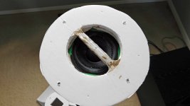
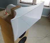
another Tractrix attempt
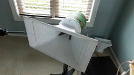
Based on the previous few posts with @GM, I made another Tractrix. Can a $10 driver (PC83) be convinced to drive a midrange horn?
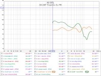
The LF roll off is around 300Hz as per the model prediction due to the small rear chamber (0.4L) plus lots of FG stuffing. The BW is extended but it still has a dip between 2Khz-4Khz. It's still the best PC83 tractrix so far, so that's progress. I'm suspecting the dip is because the T/S Mmd/Mms is correct for open air but not true if we include horn loading.
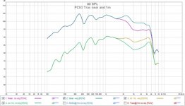
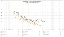
I've shown both the near field and 1m measurements with/without EQ (+6dB) for the dip. The sensitivity (1KHz) is approx. 90dB/1w@1m and in line with the model prediction. There is some ripple probably from the throat adapter cavity and foam board flex. Still it's encouraging enough to run some BEM sims to see if I can find a reason/solution to the dip.
Based on the previous few posts with @GM, I made another Tractrix. Can a $10 driver (PC83) be convinced to drive a midrange horn?
The LF roll off is around 300Hz as per the model prediction due to the small rear chamber (0.4L) plus lots of FG stuffing. The BW is extended but it still has a dip between 2Khz-4Khz. It's still the best PC83 tractrix so far, so that's progress. I'm suspecting the dip is because the T/S Mmd/Mms is correct for open air but not true if we include horn loading.
I've shown both the near field and 1m measurements with/without EQ (+6dB) for the dip. The sensitivity (1KHz) is approx. 90dB/1w@1m and in line with the model prediction. There is some ripple probably from the throat adapter cavity and foam board flex. Still it's encouraging enough to run some BEM sims to see if I can find a reason/solution to the dip.
Attachments
- Home
- Loudspeakers
- Full Range
- Dayton PC83-8 (3") test results