Gosh, Arnyk… is it really necessary to 'win' by twisting what I said? Try it again (and it remains absolutely accurate):
… the force on the speaker 'motor' coil is proportionate to the current passing through it (in the fixed magnetic field)
The force is proportionate to the current.
The fixed field (in 'modern' speakers) isn't driven by current, but perm magnets.
Don't twist what I said to mean anything different than that.
I(t) = ∫V(t)/Ldt
Seriously, dude. Like it or not, my attention to detail in physics is pretty good. It is only the limitations of coding full TeX style equations on this site that prevents me from better representing aspects of this problem. It also would be unwise: few people beyond a handful of us actually remember what-all integration and differentiation is all about.
Just … musing
GoatGuy
Perfect.Actually many years ago I build Peter Baxandal's clever V/I monitor in a Tek TM500 custom case.
Must see if I can find it back.
I remember that the display was not very clear and I needed lots of creative interpretation.
Jan
The sense resistor needs to be quite non reactive with no magfield coupled error.
The second signal (I use sine), must be a multiple of the LF signal. Otherwise, you end up with hash. Meaningful hash, but hash nonetheless.
If the second is non correlated to the primary, it becomes quite difficult to figure anything out.
John
Perfect.
The sense resistor needs to be quite non reactive with no magfield coupled error.
The second signal (I use sine), must be a multiple of the LF signal. Otherwise, you end up with hash. Meaningful hash, but hash nonetheless.
If the second is non correlated to the primary, it becomes quite difficult to figure anything out.
John
Yes that might have been the problem. Should be easy with one of those newfangled dual channel function gens.
Travelling the coming weeks so will be somewhere in March...
Jan
Actually many years ago I build Peter Baxandal's clever V/I monitor in a Tek TM500 custom case.
Must see if I can find it back.
I remember that the display was not very clear and I needed lots of creative interpretation.
Just reviewed the article, and thanks for the clear reference. It is good to see that the arts of finding URLs and cutting and pasting are not totally lost.
Unfortunately the article surely could do with some updating that the late, great Baxandall will be unable to do for himself.
The special waveform could be a .wav file. I never used any such things - various sine waves and real world music sufficed.
The use of a 1 ohm current shunt seems like way too much resistance as it is > 10% of the impedances likely to be involved.
I always used 0.1 ohm 5 watt resistors. The more common 0.22 or 0.33 ohm emitter resistors could work almost as well. Non-inductive resistors of this kind are readily available, although resistors of this kind don't ordinarily have much going on that strongly affects the normal audible band.
Last edited:
How can anything cause correction for something that isn't there?
Jan
That's the big question. Probably caused by a faulty behavior of some element in the chain. Such things can be observed, even recorded, measured, but not always explained.
The evidence is that if we correct an error which do not exist, we introduce an opposite error. Which will be corrected vrongly one more time, and so on. Such things are well known in automated mechanical machining...
Last edited:
Using that type of source, you can easily gate the secondary hf signal, make it a simple sinx/x for example, and time shift it along the primary lf signal. By doing that, you can introduce the bump anywhere along the LF ellipse. That allows probing within any quadrant. You can inspect the voltage crossovers, the current crossovers, you could even ping the foldback or limit circuitry in specific locations..Yes that might have been the problem. Should be easy with one of those newfangled dual channel function gens.
If you decide to do this, let me know, I can build you a nice 50 or 100 milliohm current viewing resistor with less than 250 picohenries inductance.
John
Using that type of source, you can easily gate the secondary hf signal, make it a simple sinx/x for example, and time shift it along the primary lf signal. By doing that, you can introduce the bump anywhere along the LF ellipse. That allows probing within any quadrant. You can inspect the voltage crossovers, the current crossovers, you could even ping the foldback or limit circuitry in specific locations..
If you decide to do this, let me know, I can build you a nice 50 or 100 milliohm current viewing resistor with less than 250 picohenries inductance.
John
Appreciate it. Coming soon to this theater
")
Jan
OK, I get all that. Then how about this: the amp sends a current trough the voicecoil and that gets the speaker moving. As a result of that, the moving voice coil generates current...
To be correct: it generates voltage (V=v*B*l), and from this voltage a current rises on impedances of the loop.
as it moves through the mag field. This current is opposite to the driving current, or not?
Yes, it is opposite or not. Depending on the actual signal and time.
If it is opposite, the amp 'sees' a higher impedance (lower net current drawn)
Yes, and this is the typical.
than with a nominal resistance.
It doesn't exist. You should compare it to DC resistance. And if you calculate the effect of back EMF, and everithing else, like skin effect, leakage inductance, eddy current, at nominal frequency you will get the nominal impedance.
If the generated current has the same direction, the amp sees a lower impedance (more current) than in the case of a resistive load.
This happens rarely, only for short periods of time and demonstrated by that mentioned impulses.
Basic effect chain: voltage-current-force-acceleration-speed-backEMF_Voltage-current_deviance.
Every "-" involves time-dependant physical effects and/or speaker-specific constant, and/or coupled effects.
And on the other side the amplifier reacts with a voltage to the load current with its frequency-dependant and nonlinear impedance what is described (poorly) by damping factor.
I can build you a nice 50 or 100 milliohm current viewing resistor with less than 250 picohenries inductance
Wow! Could you show me how to connect it? I need a 1 mohm 250 pH. Can you also do it?
Wow! Could you show me how to connect it? I need a 1 mohm 250 pH. Can you also do it?
The concept is easy by interleaved current centroids. Getting down to 1 milliohm is not.
I had pasted two pics I think in the blowtorch thread (wrong, it was feedback loop speed) showing the construction method. Should be easy to find there.
bingo.. number 278
http://www.diyaudio.com/forums/solid-state/285239-feedback-loop-speed-28.html#post4598332
The caveat is this: What we are looking for is a self inductance down in the mud to eliminate dB/dt errors caused by the resistor's magnetic field being trapped by the voltage probes used to examine the resistor's IR drop. This does NOT remove the external inductance that the resistor will present in series with the load, just removes the self inductive part.
John
Last edited:
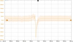
Demo of damping using jneutron's super duper current sense resistor.
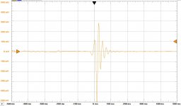
I took a biga$$ 12" woofer and carefully placed the tip of my Wiha screwdriver on the center of the dust cap and pulled it off as fast as possible to create a roughly equal relaxation from a fixed displacement under two conditions.
First I sensed the current with a .1 Ohm (jn is that what you sent me?) and gain of 90 voltage amplifier. The .1 Ohm shorts the speaker. In the second it is just the open-loop voltage. The damping should be obvious. Sometimes a simple visual display of what is going on physically is useful.
Attachments
The concept is easy by interleaved current centroids. Getting down to 1 milliohm is not.
I had pasted two pics I think in the blowtorch thread (wrong, it was feedback loop speed) showing the construction method. Should be easy to find there.
bingo.. number 278
http://www.diyaudio.com/forums/solid-state/285239-feedback-loop-speed-28.html#post4598332
The caveat is this: What we are looking for is a self inductance down in the mud to eliminate dB/dt errors caused by the resistor's magnetic field being trapped by the voltage probes used to examine the resistor's IR drop. This does NOT remove the external inductance that the resistor will present in series with the load, just removes the self inductive part.
John
Thanks! This (through hole 3D layout) is a new approach for me, I was thinking in 2 layer SMD. Still have to figure out in what path to connect it to avoid transinductance between current to be measured and sensed voltage. External inductance is also a problem at 1 mOhm, only 2...5 nH is tolerable for me...
Suggestion for terminology: you could think this network as a transimpedance with 2 ports (however on your picture these ports are not defined, but the usage is this). Instead of external and internal inductance you can say input- and trans-inductance (and -resistance). This describes the important behaviour well, and nobody will ask you where is inside and outside.
Last edited:
How can anything cause correction for something that isn't there?
Jan
That was kind of the point, but I obviously don't understand how the feedback mechanism works, which shouldn't be any great surprise
Tony.
First I sensed the current with a .1 Ohm (jn is that what you sent me?) and gain of 90 voltage amplifier. The .1 Ohm shorts the speaker. In the second it is just the open-loop voltage. The damping should be obvious. Sometimes a simple visual display of what is going on physically is useful.
So that is analogous (although not quite the same) as an amplifier with a DF of 80? If so ties up with the FOM many talk about that, once DF gets above 40 you can stop worrying about it. Or am I at the wrong end of the stick yet again?
So that is analogous (although not quite the same) as an amplifier with a DF of 80? If so ties up with the FOM many talk about that, once DF gets above 40 you can stop worrying about it. Or am I at the wrong end of the stick yet again?
https://en.wikipedia.org/wiki/Damping_factor
Damping Factor is thus the inverse of source impedance normalized by rated impedance.
IOW, DF = Zload/Zsource
The key factor is the amplifier source impedance, because it forms a voltage divider in combination with the impedance of the load.
http://hamers.chem.wisc.edu/sites/hamers.chem.wisc.edu/files/chem_628/Input%20and%20Output%20Impedances.pdf
(especially page 2)

If the source impedance and/or the load impedance have impedances that are not constant across the relevant frequency range, then the voltage divider becomes a kind of frequency dependent or equalization network.
The frequency response of this network, formed by the source impedance and impedance of the load, creates the audible and measurable effects that are sometimes attributed to damping factor. Since the mathematical relationship between damping factor, source impedance and load impedance is so simple, they can be thought of as being different sides of the same coin.
Getting back to the question, first off what is the load resistance in a damping factor spec - the nominal impedance of a speaker such as 8 ohms or 4 ohms, or the real impedance of the speaker at a particular frequency such as 24.6 ohms at 50 Hz? Obviously, only the latter is truly relevant and indicative of actual operation.
Let's say that the speaker's impedance is 40 times the source impedance of the amplifier (IOW DF = 40). Then our voltage divider has a loss of 40/41 or 0.97560 or -0.2144773 dB. This is pretty close to the best possible threshold of reliable detection of a level shift or frequency response difference. The ear is most sensitive to changes like this in the 1 KHz-5 KHz range, and only if it is very broad. Higher Q response variations at the frequency extremes are far harder (IOW impossible) to detect.
Last edited:
So that is analogous (although not quite the same) as an amplifier with a DF of 80? If so ties up with the FOM many talk about that, once DF gets above 40 you can stop worrying about it. Or am I at the wrong end of the stick yet again?
I agree with that. Nice illustration Scott!
jan
Thanks arnyk and everyone.
I read all the informative posts. From newbie's understandings it seems a modern powerful amplifier driving typical impedance speaker system almost mitigates the back emf effects. One more query. What are the effects of back EMF on digital amplifiers ?
Regards.
I read all the informative posts. From newbie's understandings it seems a modern powerful amplifier driving typical impedance speaker system almost mitigates the back emf effects. One more query. What are the effects of back EMF on digital amplifiers ?
Regards.
Thanks arnyk and everyone.
I read all the informative posts. From newbie's understandings it seems a modern powerful amplifier driving typical impedance speaker system almost mitigates the back emf effects. One more query. What are the effects of back EMF on digital amplifiers ?
Regards.
Switchmode amplifiers must have source impedances and they are often similar to the source impedances provided by many linear amplifiers, but sometimes they are worse.
If two amplifiers have the same source impedance at a given frequency then it does not matter that much at that frequency whether they are switchmode or linear.
In the real world there are many examples of switchmode amps with source impedances that rise significantly at high frequencies due to the output high frequency filter network that is outside of the feedback loop.
Linear amplifiers don't typically skate perfectly free because they often have a coil or sometimes a coil capacitor network at their outputs to improve stability. These are usually less signficant than those in switchmode amps.
Hypex modules are examples of switchmode amps with feedback around their output filters, and thus have more consistent source impedances, even at high frequencies.
If a switchmode amplifier is designed into a an active loudspeaker, then any possible frequency response variations due to the output filter can be designed into the speaker, and mitigated.
If a switchmode amplifier is part of a product like a modern stereo receiver that has a feature for measuring system response and adjusting it, then any possible frequency response variations due to the output filter can be compensated for in the adjustments to the room response, and mitigated.
Last edited:
The back EMF is always less than the applied voltage if the speaker is passive and reasonably linear.
Introduce a really strong nonlinearity like a motor-driven switch and the back voltage can go all over the place and even sometimes create a back current.
If you want to make numerical comparison, you cant avoid defining in what space do you modell the network. Time? Frequency? Complex frequency? In time-domain and with generic waveform any relation is possible in specific moments. No way you can simply compare back EMF and applied voltage, ratio varies from -infinity to +infinity with time even with a simple sinus excitation.
In frequency domain it's advisable to specify what the assumed excitation signal is like (tipically sinus) and how signals are represented (axsin+bxcos, or amplitude and phase, etc...).
Your first statement is true if you are talking about single frequency and effective values. But in this case there is no exception, back EMF will always be lower than excitation voltage, unless you make the speaker move from outside. But back EMF can be close in amplitude to the applied voltage and can have a significant phase-shift, so if you look at it in time domain, it can be reversed for a certain duration twice in every period. This is why a ClassAB amp must have a short circuit limit current much higher than 0, tipically 25...50% of max. current.
Summary: assumption of nonlinearity is not neccessary to explain the exception in time domain, and not enough in case of frequency domain, unless you are talking about generation of harmonics, but this is simply the well known distortion, i dont think really related to this topic.
- Status
- This old topic is closed. If you want to reopen this topic, contact a moderator using the "Report Post" button.
- Home
- Amplifiers
- Solid State
- Damping factor explained - or not?