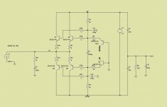
I came up with this a few weeks ago. Performance is not that good, but maybe it just needs some different transistors. I'm not experienced enough to know for sure.
Dirk i will take a look to your circuit tomorrow..
Now is time to go to the beach.
Tchau
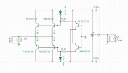
Here we go.
The BC327 are also the high Hfe -40 group.
That looks interesting. I'll give it a whirl in Tina.
Thanks...
I don't think the BC337-25 and BC327-25 are true complements because I get different currents in R5 and R6. It was worse when I used the BC337-40.
Attachments
Joachim,
have you try a capacitor in parallel with R13?
if not try 4nf , it will cut at 200khz,
if this will not result try to take out one pair of bc327/337 of the input, or try the same circuit with transistors with lower Cob.
keep us inform.
edit: which frequency it oscilate?
what is the input capacitance of the source you use?
Last edited:
I came up with this a few weeks ago. Performance is not that good, but maybe it just needs some different transistors. I'm not experienced enough to know for sure.
Dirk have you already try in practice build a circuit without emitter resistance at the input?
it seems a bit risky , as the variations in temperature will increase current and this is a positive feedback mecanism.
You can do that for jfet and some types of mosfet like lateral type but not with transistors .
I assumed the current mirror would force it to stay constant.
Dirk have you already try in practice build a circuit without emitter resistance at the input?
it seems a bit risky , as the variations in temperature will increase current and this is a positive feedback mecanism.
You can do that for jfet and some types of mosfet like lateral type but not with transistors .
You're right, I need to build something myself and let it cook for a while to see if there's a problem. I can hack something together later.
At last i found the problem. It was a faulty voltage devider behind my generator.
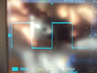
This has cost me at least 8 hours. i had it under suspicion, i told you before. First i modified it for pseudo balanced because i thought it would be a grounding issue because of the floating SEN character. That did not help. Then i measured the output with 1 to 10V AC in and nothing came out ! I used another voltage devider ( 1kOhm / 6 Ohm ) and VOILA; it works. The version with 2.2nF loading goes to 650kHz and the square is clean. It works also without the 2.2nF. FRQ is then up to 4.5MHz -3dB with an overshot.
I also measured current in the various transistors and did not find any big disparity dispute Dirks simulation. It is 80mV over 5.1 Ohm in the input transistors and 90mV over 30 Ohm in the helper transistors. PNP and NPN have differences only in the mV range so symmetry of currents is good. That transfers into 16mA idle in each input transistor and 3mA idle in the helpers. That looks reasonable.
I will tell you more plus some photos.
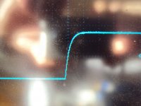
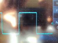
Here are some pictures.
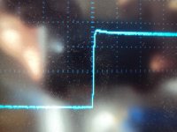
10kHz undamped
10kHz undamped zoom
10kHz damped
10kHz damped zoom
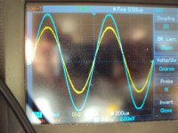
Gain
Gain is ca. 34 x although 160 / 6.6 = 24.24 x was expected, even less when the input impedance is counted in.
This stage does not have a pure transimpedance but also some voltage gain. Positive feedback ?
10kHz undamped
10kHz undamped zoom
10kHz damped
10kHz damped zoom
Gain
Gain is ca. 34 x although 160 / 6.6 = 24.24 x was expected, even less when the input impedance is counted in.
This stage does not have a pure transimpedance but also some voltage gain. Positive feedback ?
Attachments
- Status
- This old topic is closed. If you want to reopen this topic, contact a moderator using the "Report Post" button.
- Home
- Source & Line
- Digital Source
- dac I/V convertion with very low distortion