Things go slow here, it is extremely hot outside so i am more in the mood to digest a cold drink. Tonight i will go to cinema with my son. Prometheus by Ridley Scott.
c'est la canicule
I did not know it reached there also Joachim. I am drinking two litres of water everyday. (And I live at 700m)
HAHAHA. Running an LME49600 backwards! I need a drink.
Dirk I was only half kidding

Look at the datasheet of the lme49600 buffer and you will see that the internal circuit is very similar to the joachim circuit.
I need a
tooBack in the late 90's I hacked that Shinja idea into a Dennon CD player that I think used PCM63's. I used the OP275 too. The whole thing was inspired by the Alexander curent feedback power amp design. I used a conventional grounded center tap power supply fed to the opamp through a cascode, and an output stage driven from it made out of low voltage signal transistors. The sound was pretty killer. Actually it was one of the best CD players I had, with the I/V convertor on a breadboard!
Another 275 was used for a a few poles of low pass filter and I dumped it straight into a Hafler DH-120 with no buffer.
Another 275 was used for a a few poles of low pass filter and I dumped it straight into a Hafler DH-120 with no buffer.
Last edited:
c'est la canicule
I did not know it reached there also Joachim. I am drinking two litres of water everyday. (And I live at 700m)
He's German, do you really think he's drinking water???
Dirk I was only half kidding
Look at the datasheet of the lme49600 buffer and you will see that the internal circuit is very similar to the joachim circuit.
I need a
OK!
I thought the LME49600 was just a fancy diamond buffer?
In Denmark we have 30 degrees...I sit outside enjoying the fine weather... drinking Iced tea..skipped tha food as i have been eating way too much on restaurants lately....
I really hope this leads somewhere...I have a concept that i would like to post, but it does not have the really strong point of the circuits here ....the elegant handling of the base currents... but it's more a final servo-ed circuit that could be PCB'ed built and work.
I really hope this leads somewhere...I have a concept that i would like to post, but it does not have the really strong point of the circuits here ....the elegant handling of the base currents... but it's more a final servo-ed circuit that could be PCB'ed built and work.
I think smms73 realy ment to use the output of the LME49600 as input then ground the input ( there is a 200 Ohm resistor in series ), use a floating supply and couple out the signal like in the SEN, CAN with electrolytics and ballast resistors. It COULD work, The internals of the LME49600 are scary similar to smms73s input stage but "the other way around", so smms73 input stage is in fact an "inverted diamond buffer". If that works or not i can not tell but i have some BUF634 that are very similar and i could simply build it and test it. Just for fun.
Cuurent consumption of the OPA1641 is very low at 1.8mA.
The batteries will last forever ...........
Ok. let's think for a while...
The dac output 7.8ma pp but the quiescent current of the opa1641 is only 1.8ma.
This will make the output transistores of the op amp work in class B.
Thats the reason i say to use a buffer or a discrete op amp with a greater quiescent current.
But as the dac has a -6.2ma offset current, maybe the opa1641 will be in class A.
one way or another you will have a close feedback loop, so maybe is better to use a classical i/v (no need for battery) .
But this start to be a joke of Shinja, then why not build it just for fun
I really hope this leads somewhere...I have a concept that i would like to post, but it does not have the really strong point of the circuits here ....the elegant handling of the base currents... but it's more a final servo-ed circuit that could be PCB'ed built and work.
Please do post your circuit.
I´m sorry the evolution is a bit slow, but things are moving.
Sadly, i have discover that the relative high Cob of the bc227/327 increases instability,
especially in the output transistors. So, for now i will be using 2n3904/3906 for testing porposes, and wen i have a working prototype i will try with others transistors.
If someone knows of a transistor with low base spreading resistence and low Cob please inform.
One good quad transistor seems to be the that300 made by thats corporation ( Rbb of 25 ohm and 3pf cob),
The internals of the LME49600 are scary similar to smms73s input stage but "the other way around", so smms73 input stage is in fact an "inverted diamond buffer".
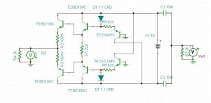
Yes Joachim its a diamond buffer, the circuit can achieve very low distortion, because don´t have voltage variations, in that way we get rid of distortion cause by Cob variations and BJT Zout, and of course the base currents.
This circuit just work as a all. If you want the low distortion that this is capable you have to use it like that.
> The dac output 7.8ma pp but the quiescent current of the opa1641 is only 1.8ma.
If you use PCM1704, then Iout is 1.2mA, and I am still in Class A with the OPA1641.
For a DAC with 8mA Iout, you can use 5x OPA1641 in parallel, the brutal way.
> But as the dac has a -6.2ma offset current, maybe the opa1641 will be in class A.
That will solve it, using the offset current to bias the OPA.
> one way or another you will have a close feedback loop, so maybe is better to use a classical i/v (no need for battery).
Or use a passive IV (someone suggested 0.8R at the other thread) and amplify the signal 100x ??
Patrick
2sa1015/2sc1815 is 30Ω/50Ω of rbb and 4pF/2pF of Cob.If someone knows of a transistor with low base spreading resistence and low Cob please inform.
these transistors are very popular in japan, for general purpose .
2sa970/2sc2240 are much low noise ,so it must be smaller rbb, but no informations on the datasheet.
other japanese small signal, through hole transistors for low noise purpose (such as MC head amp) are all gone.
the rests will be discontinued soon.(above listed too)
they are already NRND status.
- Status
- This old topic is closed. If you want to reopen this topic, contact a moderator using the "Report Post" button.
- Home
- Source & Line
- Digital Source
- dac I/V convertion with very low distortion