Yes is strange. I understand this well. That because I think one may know more about this effect... It is possible that myself, or Joe, or Ken can take wrong what we hear. But when many other it will have the willing to try it and investigate more, then maybe some things will come up... This is the logic/meaning to start this thread.
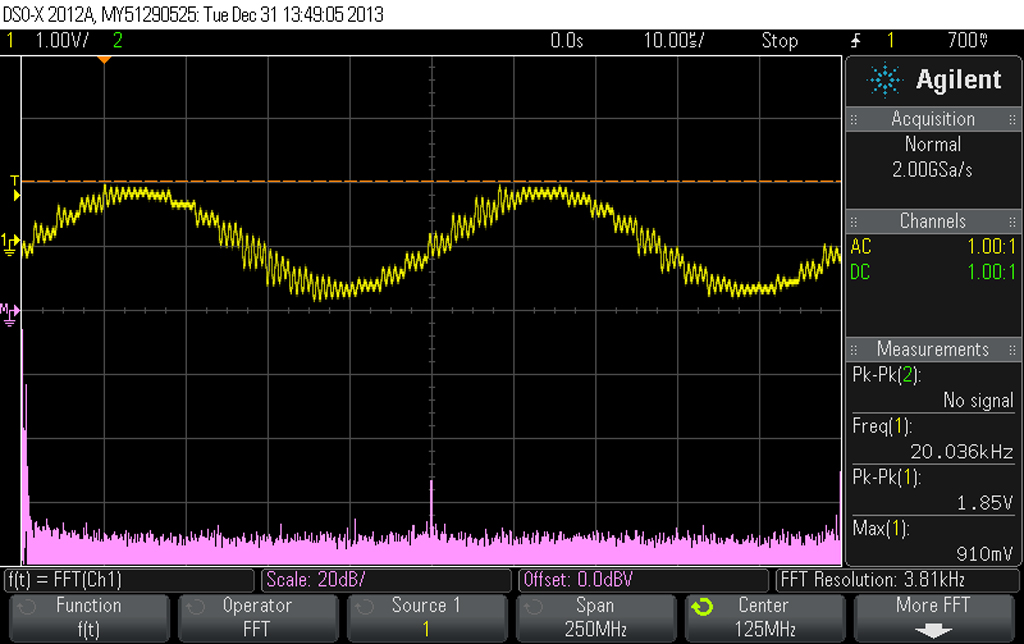
Now, about the HF noise. This noise is not a osculation from the opamp. Its shapes shows well that is the residual noise coming from the DAC, which is processed/amplified further by the opamps. It is this noise I refer and you may see it in the pictures. This noise is around 300Khz. Without these caps across the phases, this noise (the same shapes/characteristics) still exist in a non filtered DAC system, and is to be found on RCA outputs. In my case, this noise is few hundred mVpp (which I can reduced its amplitude without filters to few teens mVpp). With the caps soldered across the phases this same HF noise increase in level, as the caps increase in values, until a critical level. Then, the noise level increasing it happen abruptly degrading the useful audio signal. This HF moderate level (with the right cap in place) is for a 16Vpp useful signal in the same measured point. I can hardly see that this HF noise have an impact over the audio spectre signal so to alter the heard sound quality. BTW, as I said before, and Ken confirmed too when about his system, the quality of the sound outputted is much better without any "classical" filtering between I/V and final.
So, implementing this Rasmussen filtering, the very good quality of the sound outputted in my system, it become even better. There is not here about high and low frequencies in audio spectre which are to be heard better. There is a obvious improvement in the sound stage, the weight of the sound, dynamics, and so on. There is about details of a already high fidelity sound. There is like this in my perception, but how I could see, there are the similar improvements reported from others, using another types of DACs or systems set up. So it have to be something in this....
Last edited:
Thanks for this helpful advice Coris.You may try yourself... (DIY) And then comment here your conclusions.
There is very simple to try this trick. Just solder a cap over the differential output of your DAC before I/V. You may start first with quite low capacity values. If you can hear some changes in the quality of the outputted signal, then you can experiment further increasing the caps value. Is not easier than this! And not any damage/danger for your system.
I'll certainly try to explore this. Looking at the DAC board, the component side is quite stuffed so this experiment will find a place at the bottom side.
Ugh... Considering the illustration given, the effect would be zero with a perfect I/V converter. Since nothing is perfect, it forms a differential single-pole filter with the parasitic resistance of the I/V converter. There's nothing magical about about it. Standard textbook stuff...
Ugh?
the effect would be zero with a perfect I/V converter...
We know that - as I said when I posted last night, I would furnish suggestions and techniques dealing with that. A filter cannot work at zero Z, and we have not attempted that.
Yes, we kind of expected this sort of dismissive attitude. But please do read the finer print, so to speak. We are seeking more than just the effect of a differential filter here.
This filter is more 'dominant' in the sense that it does something that is not normally considered kosher, it will be measurably down at 20KHz, and that is new.
Filtering below 20KHz? Can you see why that has been resisted so far ???
In the case of a "voltage" out DAC, indeed what you call the parasitic output Z of a "voltage" DAC is low and it needs the R of the RC to be boosted. I would recommend something like 47R in series with each phase. Then the actual Z will be equal to the sum of the two values, one known and the other will be fairly low too. You could of course measure it.
Then adjust the 'differential' cap value to give you -1.3dB or slightly more @ 20KHz, and then take a listen. This may well be the sweet spot across a broad number of delta-sigma DACs (remains to be seen), adjust cap or even resistors within reason.
The cap value can be quite large, and in some case as high as 1uF. Not a common filter cap value I would think.
Again, this kind of 'dominant' filtering does not make the DAC sound rolled off. It does not make the DAC sound slower, unless you have over-cooked the cap value and need to back off.
Let me give you an example, with a value of .039uF and passive I/V set to 3R3 x 2, it was about 0.4dB down @ 20KHz and did little (and in fact may have been worse), but adding another 0.39uF in parallel (now 0.78uF in total) made the filtering really bite and brought it to -1.3dB - and it made quite a difference.
There will be further skepticism I know... but gradually, the more who do it, then the number of armchair critics will diminish.
To quote John Curl: "Condemnation with Examination is Prejudice" - in fact he named his 'book' thus.
Read: "Condemnation with Examination is Prejudice" by John Curl
Cheers, Joe
.
Last edited:
I thought at a theory about these strange things.
The effect it works so as improvements it happen obviously in the perceptual sound stage. What does it mean this? There is much easy, or just possible to identify/locate the sources of the components of the sound outputted in stereo set up.
As we knows already, the human being locate the sound sources around by the microscopic delay in the phases of the sounds which are to different hit the two ears of somebody. This identification of sound sources position it not work well at all if one hearing is only one channel (one ear). The same as we can appreciate the depth of objects or distances, by looking at something with both eyes, but not only with one.
So, using this cap in that place, filtering in this way, It may happen something, it may be an improvement in the phases domain of the components in a audio signal. It may be more accuracy in reproduction of these audio component phases at the input if the I/V stage, and further in the system, so that the sounds are reproduced in a manner which it make possible for the brain to identify the delays of the sound components, and so locate the sound sources coming out through the two stereo channels.
These caps and its effects it may contribute to a more accurate reproduction of the audio signal in the system.
This it may be my (for moment) explanation, or speculation...
Last edited:
Was the -1.5dB @ 20KHz measured or calculated ? (ie, where does this number come from ?)...
I don't recall reading how Joe first came to make his observation. I assume that, like many discoveries, he stumbled across it accidentally while exploring some other avenue. After reading Joe's comments about the effect, I independently observed the effect. After that, I arrived at my own subjective effect detection threshold figure of -0.5db @ 20KHz via empirical listening experiments, using various filter response curves. Joe's recommendation of -1.3dB to 1.5db @ 20KHz, however, does sound close to optimum to my ears.
Is this audible effect most evident when both stereo channels have been treated or is there an audible affect with only one channel?
Good question - I have only done it in Stereo and kept both channels the same. One of the really big gains is what it does to the soundstage; depth,height, width and all that. But it just doesn't make it sound bigger in some artificial way (which would be even harder to explain how), but within the soundstage there is so much more precision. And when the soundstage is not required, it collapses as it should because it is not there.
So while I do think it will be heard Mono, I do believe it will be heard more effectively in Stereo. And the benefits are not just in the soundstage.
Cheers, Joe
PS: We hear that word "soundstage" a lot (my spell checker doesn't recognise it) - but there is also the "sound-space" and while they are related, they are not the same. The soundstage is the location that can be heard in its entirety, the sound-space is what we hear within the soundstage, the individual instruments and voices having their own individual space. The 'effect' discussed enhances this to a significant degree - they are both important. They should be more obvious in Stereo.
.
Joe,Ugh?
We know that - as I said when I posted last night, I would furnish suggestions and techniques dealing with that. A filter cannot work at zero Z, and we have not attempted that.
Yes, we kind of expected this sort of dismissive attitude. But please do read the finer print, so to speak. We are seeking more than just the effect of a differential filter here.
This filter is more 'dominant' in the sense that it does something that is not normally considered kosher, it will be measurably down at 20KHz, and that is new.
Filtering below 20KHz? Can you see why that has been resisted so far ???
In the case of a "voltage" out DAC, indeed what you call the parasitic output Z of a "voltage" DAC is low and it needs the R of the RC to be boosted. I would recommend something like 47R in series with each phase. Then the actual Z will be equal to the sum of the two values, one known and the other will be fairly low too. You could of course measure it.
Then adjust the 'differential' cap value to give you -1.3dB or slightly more @ 20KHz, and then take a listen. This may well be the sweet spot across a broad number of delta-sigma DACs (remains to be seen), adjust cap or even resistors within reason.
The cap value can be quite large, and in some case as high as 1uF. Not a common filter cap value I would think.
Again, this kind of 'dominant' filtering does not make the DAC sound rolled off. It does not make the DAC sound slower, unless you have over-cooked the cap value and need to back off.
Let me give you an example, with a value of .039uF and passive I/V set to 3R3 x 2, it was about 0.4dB down @ 20KHz and did little (and in fact may have been worse), but adding another 0.39uF in parallel (now 0.78uF in total) made the filtering really bite and brought it to -1.3dB - and it made quite a difference.
There will be further skepticism I know... but gradually, the more who do it, then the number of armchair critics will diminish.
To quote John Curl: "Condemnation with Examination is Prejudice" - in fact he named his 'book' thus.
Read: "Condemnation with Examination is Prejudice" by John Curl
Cheers, Joe
.
I don't doubt that there is filtering. I just doubt that there is anything other than a simple first order low-pass here.
As for the comparison to a a voltage output DAC, it's not limited to a voltage output DAC. An I/V stage must have a low impedance not to violate the voltage compliance of the current source output DACs. It is that low impedance that is forming the R for the low-pass filter with your added C, not the impedance of the DAC.
Good quote from John Curl, but it doesn't apply here. One can examine without actually adding a capacitor. Examination can include mathematics and knowledge of electronics. That's the foundation of engineering. Not throwing caps around. I do not have to perform the experiment to reliably say that all you have is a single pole low-pass filter.
Furthermore, disagreeing about the claim that this is some sort of magic that transcends all that is known about electronic circuitry does not constitute the role of "arm chair critic." You're not likely to have anyone pay much attention to your argument when you dismiss all that disagree with such quips.
You should be aware that I'm not claiming there is not difference. I'm only claiming that it is nothing more than a low-pass filter. There is nothing magical about your capacitor placement. It works as a filter and you hear the results of that. As others have pointed out, it's not the best place for a capacitor as it increases the noise gain and worsens stability if the I/V converter is an op-amp. But, it does function as a filter.
Your example backs that up. You've illustrated a great example of the single pole filter I speak of. Draw the output of your DAC as a current source, draw the input resistance of the I/V, a little Norton and Thevenin, and you have a single pole low-pass. Now do you see how I can say this without modifying anything?
By the way... Thanks for the book link. While it doesn't support the claims you made about my dismissive attitude towards your magic, I'm sure it'll be a good read.
Last edited:
Yes, I understand from the descriptions so far given that it seems to be stabilising the soundfield in some way, resulting in either more accurate ITD or ILD or both. It may also be attenuating the noise modulation of SD DACs as you pointed out on the other thread? I just thought that listening solely to one channel would help tease out some of this or at least give some further data points
This area of psychoacoustics (localisation & Audio Scene Analysis) is still not fully understood & being actively researched, so there may be other, more complex psychoacoustic reasons for this effect
This area of psychoacoustics (localisation & Audio Scene Analysis) is still not fully understood & being actively researched, so there may be other, more complex psychoacoustic reasons for this effect
Last edited:
seems if you call warm water as TAIL (thermal agitated isotropic liquid), it's no more warm water ") Try it
Try it
For engis, words are only "a way to understand each others based on a reference" so we can call warm water in thousand of ways..but it's still objectively H20.
Which means that now, i understand what Rasmussen effect is: a cool way to call a filter effect
Easy. Clear. Simple. Not arab.
Try it For engis, words are only "a way to understand each others based on a reference" so we can call warm water in thousand of ways..but it's still objectively H20.
Which means that now, i understand what Rasmussen effect is: a cool way to call a filter effect
It's a single pole lowpass. If by phases you mean the differential output, it's still a single pole, just differential instead of common mode.
Easy. Clear. Simple. Not arab.


Joe,
I don't doubt that there is filtering. I just doubt that there is anything other than a simple first order low-pass here.
As for the comparison to a a voltage output DAC, it's not limited to a voltage output DAC. An I/V stage must have a low impedance not to violate the voltage compliance of the current source output DACs. It is that low impedance that is forming the R for the low-pass filter with your added C, not the impedance of the DAC.
Good quote from John Curl, but it doesn't apply here. One can examine without actually adding a capacitor. Examination can include mathematics and knowledge of electronics. That's the foundation of engineering. Not throwing caps around. I do not have to perform the experiment to reliably say that all you have is a single pole low-pass filter.
Furthermore, disagreeing about the claim that this is some sort of magic that transcends all that is known about electronic circuitry does not constitute the role of "arm chair critic." You're not likely to have anyone pay much attention to your argument when you dismiss all that disagree with such quips.
You should be aware that I'm not claiming there is not difference. I'm only claiming that it is nothing more than a low-pass filter. There is nothing magical about your capacitor placement. It works as a filter and you hear the results of that. As others have pointed out, it's not the best place for a capacitor as it increases the noise gain and worsens stability if the I/V converter is an op-amp. But, it does function as a filter.
Your example backs that up. You've illustrated a great example of the single pole filter I speak of. Draw the output of your DAC as a current source, draw the input resistance of the I/V, a little Norton and Thevenin, and you have a single pole low-pass. Now do you see how I can say this without modifying anything?
By the way... Thanks for the book link. While it doesn't support the claims you made about my dismissive attitude towards your magic, I'm sure it'll be a good read.
There are a few issues with this thread (and the original) that, because of a
lack of some kind of technical guidance if you will, we have an endless
procession of forum bandwidth waste and a good dose of confusion as well.
I'd like to try and clear things up for new comers:
- We have 2 distinct filter topologies here and they are quite different.
a) Joes application is of a differential RC low pass filter as he is running
his DAC in 'voltage' mode, into a very low resistance value. There are
some secondary effects such as noise increase at HF and higher distortion of
open loop I-V, but that may also be perceived subjectively as an
improvement - it depends.
b)Coris' application is not really a low pass filter per se but actually a
compensation adjustment. In this 'filter' the DAC runs into a differential
opamps virtual ground and it is in true current mode, IOW -no- voltage swing
at DAC OP.
However the cap that Cooris has put across the DAC OP (opamp IP) will cause
a few things to happen: - It will change the compensation of opamp. The
1632 is no ordinary opamp and it appears to be very tolerant of this 'filter'
cap , probably because of the very low open loop gain, listed as 78dB at DC
in data sheet. How successful this cap-a-x-dac scheme would be with normal
opamps is questionable but I would proceed with caution and a good cro
- The second effect is the noise gain of the 1632 will be dramatically raised at
HF. Again, Coris you lucked out as the 1632 has very low noise so as they
say 'half your luck!
WRT Joes voltage mode LPF - this is not really new and many people,
including myself have used it over the years in many forms. It's pretty much
the first place to put a LPF if you have a voltage OP DAC - before any
active electronics.
I can show you a box of these 'pre I-V' LPF's I have used over the years. Air
cored LC, LRC, RC, transformer integrated, etc etc.
There was a comment WRT some magical interaction with sinc dig LPF, I
don't think so. I think it is just attenuating HF energy before any active
electronics have to - which is always a good thing.
Coris if you wish to try Joe's true 'voltage mode' low pass filter with your
existing differential opamp ref to schematic below. R IP 1/2 can be chosen
together with appropriate cap size to get required HF rolloff. This scheme will
increase the noise gain at HF but you should have no stability issues.
Values of IP R could be any where from 20 ohm -> 3ohm. The lower the R
value the larger the cap must be for given HF roll off. The larger the value of
IP R the more the DAC will work in 'voltage mode' with it's sonic impact.
There are more options such as small C's on each RFB to reduce HF gain.
As you can see there are a myriad of options when applying to an active
opamp based I-V and yes - a lot of us have tried most of them too.
In the end many just move on from opamp I-V's to good discrete circuits
and the rest is history.
cheers
T
edit PS I think the phases are *** about on that diag but you know what I mean
Attachments

Last edited:
Just to add my voice to this discussion - in a positive sense! I'm very much aware of the quite dramatic improvements in sound quality possible when all the right things are done, and you gentlemen have appeared to discover a quite simple shortcut to that end, which works in at least some situations. I'm very impressed with the investigative efforts so far, and I bid you fair winds in your further journeys!
As just suggested in a post, this 'effect' - which is actually the elimination of a major distortion component - could very much be due to some parasitic oscillation, which is unknown to everyone but is a normal by-product of most such circuits, being either snubbed or detuned sufficiently by the cap, allowing the DAC and the following circuitry to behave as they're meant to, as the datasheets claim they should ...
As just suggested in a post, this 'effect' - which is actually the elimination of a major distortion component - could very much be due to some parasitic oscillation, which is unknown to everyone but is a normal by-product of most such circuits, being either snubbed or detuned sufficiently by the cap, allowing the DAC and the following circuitry to behave as they're meant to, as the datasheets claim they should ...
Drastic change in sound quality is often caused by HF oscilation.
In an interesting way, that's essentially what I suspect is going on. I doubt the effect is attributable simply to frequency domain filtering of image products, because the filter is only first order, and the effect dissappears by changing the response of that filter by only a few tenths of decible at 20KHz.
My intial thought is that the in-band filter roll off point is helping to 'window' the digital filter SINC reponse function enough to usefully mitigate Gibbs impulse phenomena, which looks like a damped oscillation. If set near -1.5db @ 20KHz, I wonder whether the output filter then critically dampens some of that Gibbs ringing. However, that's just conjecture for now. I'd need to perform an impulse response test to further explore this.
Last edited:
I don't recall reading how Joe first came to make his observation. I assume that, like many discoveries, he stumbled across it accidentally while exploring some other avenue. After reading Joe's comments about the effect, I independently observed the effect...
Thanks Ken, for landing that one in my lap.
Gut instinct based on years of experience?
That would be the short story, the long story would be quite long and boring. I will try to keep it concise. Hard to know where to start.
I come from a loudspeaker and amplifier design background, of the latter I do tube and tube hybrids as well as some products that are solid state, they all have unconventional elements. On speaker design, I have designed a 2nd Order Butterworth Alignment that can be current driven (it can be driven from any source Z and the alignment does not change - and there is no way I could have done that, right?). I was a sounding board for the late Allen Wright, whom I met in 1975, and there was a third guy called Rowan McCombe whom Allen affectionately called The Guru. In those days, nothing was sacred and everything was questioned.
I also became interested, with Allen, in live recordings. And here is the first pointer, Condenser Mics versus Ribbon Mics. The Condensers had a signature that made them sound at HF in certain ways, but listening to Ribbons, which were far more extended and clear in the highs, and lower distortion, yet to 'taste' they sounded rolled off in the HF as people had been conditioned to listening to Condensers. There was a perceived lack of energy in the Ribbons, but in fact there was excess energy in the Condensers not revealed nor explained by any conventional Frequency Response, FR.
This started thinking about the audible influence of excess energy, where FR would not indicate this. I further found there was an equivalence in loudspeaker design, lots of them, where FR and what was perceived were not necessarily in step with the other. Over the years I have come across other examples of that. For example, we can say that speakers have many FRs (just put the Mic somewhere else and you have a different FR), but it only has one Power Response.
Take the perception of speed in audio. When we think of fast cars, we think of acceleration as defining speed. We don't think too much about the fact that a fast car, and the even faster car, needs better brakes.
In audio, speed is not a function of FR, where greater acceleration needs greater FR or bandwith, but from a perception point of view, it is de-acceleration that defines speed.
This is very easy to explain and to understand, when you come from a loudspeaker background, where you constantly have to deal with damping. Here we talk about tight bass and the fact there is no overhang when a speaker's alignment is well designed, it is tight and fast sounding. It is also clean sounding. It also shows an absence of excess energy and again FR may tell you nothing. It is the stopping power where excess energy is properly damped that imparts speed, and often optimum damping will also be the most informative in terms of detail revealed.
Look up the published slew rate of Audio ICs, they will always have the usual bandwidth ratings, but what I hone in on is the settling time they publish. The true speed of an amplifier is actually its settling time and the lack of excess energy.
I don't want to drone on, but I think you get the general idea. When listening to Ladder DACs and the fact that some people are totally in love with NOS-DACs, then maybe they are perceiving something that innately bothers them about delta-sigma DACs. Again I look at noise shaping and dither and start to wonder...?
Here is another loudspeaker tip - we say that a first order filter (Crossover) does not ring, unlike multi-order filters can. The use of LR2 and LR4 filters that choose a Q=0.49 is clearly the fact that <0.5 is 'critically damped.'
So whatever is going on, like a lot of damping techniques, there is always a sweet spot.
So I am quite familiar with some damping techniques, both mechanical and electrical. Again I can give numerous examples, but I use it in power supplies and I fit very large stacked ceramic film capacitors (I now realise others are doing this too, but we started this very early on) and especially fit these close to the power supply pins on DACs. The form a nice LC filter to attenuate power supply derived noise (the track to the cap is an inductor at VHF), but most importantly it absorbs back-EMF from the DACs itself, which one big bunch of switching circuits and hence DACs are like human producing CO2 that are harmful and needs to be absorbed or dissipated or poisoning your own environment. Again, as with speakers, back-EMF is a natural for me to think about. Power supplies needs to be damped when driving noisy circuits.
In back-EMF terms, everything is an input.
So a whole bunch of things also pointed to the output of delta-sigma DACs. The Ladder DAC and NOS-DAC guys may have a point and are hearing something that bothers them...
So I had an instinct and I followed it. That's it.
And I found it had a sweet spot.
Note that all this comes from a very analogue viewpoint.
After that, I arrived at my own subjective effect detection threshold figure of -0.5db @ 20KHz via empirical listening experiments, using various filter response curves. Joe's recommendation of -1.3dB to 1.5db @ 20KHz, however, does sound close to optimum to my ears.
Maybe, if that is proved consistent, that could prove significant. One, as a pointer to what is going on, and two, makes it a lot easier and practical.
We shall see.
Cheers, Joe
.
Last edited:
Good quote from John Curl, but it doesn't apply here.
It isn't the vibe I am getting from you.
One can examine without actually adding a capacitor. Examination can include mathematics and knowledge of electronics. That's the foundation of engineering. Not throwing caps around. I do not have to perform the experiment to reliably say that all you have is a single pole low-pass filter.
Seems to me worthwhile just getting a soldering iron out.
Then we can do both before and after.
Who comes first, the experimental scientist or the theoretical scientist? Truth is that it could be either one. But I do wonder what would have happened if experimentalist Faraday (he invented the motor by the seat of his pants and nothing more) had not predicted that light was electromagnetic waves (and got a right bollocking for suggesting it) and Maxwell, the mathematician and theorist, decided to prove Faraday right. Without those two, Einstein is unlikely to have come up with E=MC^2.
The World would have been poorer if there were no Michael Faradays. And that is what you are suggesting.
You can not simulate everything in the world, and what you call engineering is more than just brain storming - that is only part of it. The rest is often only hard won after a lot of sweat and toil.
But in putting this out there, I was waiting for you even if I did not yet know your name, I was waiting for you and there you are. Sigh.
Would it have made you happier if I had just kept it to myself? Double-sigh.
I do not have to perform the experiment to reliably say that all you have is a single pole low-pass filter.
And neither do I - and that is hardly the point.
We are not trying to prove whether it is a filter or whether it is not. That is like trying to prove it is raining when it is raining.
It is a filter - what we need to understand is what this filter is doing. On that I am very open to suggestions. Maybe if you could come on board, then you may well contribute a positive thought on that - and it would be most welcome.
In the meantime, please don't sound so condescending, please...... OK?
Cheers, Joe
.
It seems some guys here have tried this on passive IV, like :
DAC -> RC filter -> output
In this case, it is a simple linear passive filter and we can talk about frequency response. No problem here.
However when an opamp IV enters the picture it is a completely different thing. The following is about this case.
Let's spice it : a textbook OPA1632 I/V with 1mA differential current at the input, 1k IV resistors and 1nF feedback cap. -3dB point at about 160kHz.
Attachment 1 :
Sim with and without "C1" (3nF cap at the opamp input).
As expected the lowpass rolloff point does not change. All the cap does is add some nice peaking around 10 MHz.
Attachment 2 :
Same, with more "violent" values for C1, up to 100µF, stepped in decade. To get some change of frequency response in the audio band, at least 10µF is needed.
Coris, if you have a different circuit (making this sim irrelevant), please tell us about it.
Attachment 3 :
Transient simulation. No added capacitor.
Top curve, input current. Middle curve, voltage at opamp input. Bottom curve, output.
Opamp and its feedback caps behave as first order lowpass.
No problem here, everything behaves as expected. Which means it doesn't work : opamp goes in slew limit, input voltage is large, upsetting the opamp input stage, peaks of output voltage have ugly warts (see zoom insert), etc. That's the usual opamp IV, I guess that's why some don't like it...
Attachment 4 :
Transient simulation. Added capacitor at input.
Reduced phase margin makes opamp less stable. The input waveform is a mess. Output shows signs of ringing too.
Attachment 5 :
Removed feedback caps. Tweaked circuit values to get ringing similar to this trace.
Attachments


Good question - I have only done it in Stereo and kept both channels the same. One of the really big gains is what it does to the soundstage; depth,height, width and all that. But it just doesn't make it sound bigger in some artificial way (which would be even harder to explain how), but within the soundstage there is so much more precision. And when the soundstage is not required, it collapses as it should because it is not there.
So while I do think it will be heard Mono, I do believe it will be heard more effectively in Stereo. And the benefits are not just in the soundstage.
Cheers, Joe
PS: We hear that word "soundstage" a lot (my spell checker doesn't recognise it) - but there is also the "sound-space" and while they are related, they are not the same. The soundstage is the location that can be heard in its entirety, the sound-space is what we hear within the soundstage, the individual instruments and voices having their own individual space. The 'effect' discussed enhances this to a significant degree - they are both important. They should be more obvious in Stereo.
.
Yes, this is definitely an effect in strong relation to the sound stage and/or sound space. As the sound stage is determined at least by two channels, then one may have the two stereo channels up to make the things up and running.
But I wonder now how it may "sounds" all this in multi channel set up.
So, they who have a such functional system (best an Oppo player), it will be very interesting to do the experiments. And maybe give us a sign about their results. I personally own a Oppo player, but I do not have (not so much interested in this at least...) a multichannel amplifier/speakers system.
Very exciting to hear about experiments in multichannel with the "Rasmunssen Effect"...
seems if you call warm water as TAIL (thermal agitated isotropic liquid), it's no more warm water
For engis, words are only "a way to understand each others based on a reference" so we can call warm water in thousand of ways..but it's still objectively H20.
Which means that now, i understand what Rasmussen effect is: a cool way to call a filter effect
Easy. Clear. Simple. Not arab.
The only difference between this "single pole" Rasmunssen filter (cap across the DAC differential output), and a classical single pole filtering technique (caps over the I/V feedback resistors, or even more sophisticated filters between I/V and final opamp), it is that while the Rasmunnsen filtering produce the effect we discuss about, the another classical filtering does not...
One will never get the same obvious sound scene/space definition and accuracy when using classical ways of filtering. I have been struggling with this a lot, I may say, and suddenly this simple "single pole" cap across the DAC differential output it gave me what I was looking for.
At last is very little important how one may call this kind of filtering. More important is to be found out why placing of this cap in that place it produce this effect.
Suggestion for Current DACs:
This will be the most common config using ICs and Virtual Earth. Also my least favourite.
The cap value shown is only a rough suggestion - aim to adjust value to be -1.3dB to -1.5dB @ 20KHz.
Note in this case, the cap is before the resistors and since the resistors are between the cap and the Virtual Earth, those resistors define the R of the RC filter.
Attachments

Last edited:
- Status
- Not open for further replies.
- Home
- Member Areas
- The Lounge
- DAC Filtering - the "Rasmussen Effect"