quoting the index of post #1Measurement results and comparisons:

I have used a Dienoiser in the sensitive section of a frequency synthesizer, and I noticed that for 6V the values from the table published by Diego are not optimal.
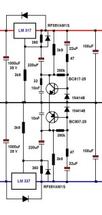
This is the modified circuit:

With the original values, the the Vce of Q1 was <1V, which is not very healthy: the transistor works in quasi-saturation mode, and the possible correction amplitude is limited.
With R3 at 470 ohm instead of 1K2 and R5 connected differently, the collector voltage is more reasonable, and the current through Q1 is higher, which is beneficial for the noise performance
This is the modified circuit:
With the original values, the the Vce of Q1 was <1V, which is not very healthy: the transistor works in quasi-saturation mode, and the possible correction amplitude is limited.
With R3 at 470 ohm instead of 1K2 and R5 connected differently, the collector voltage is more reasonable, and the current through Q1 is higher, which is beneficial for the noise performance
The table was prepared only from simulation results, as they have not been obtained from real tests on a test bench. That shows that simulations could give a rough approximation to the results, but not as accurate as those of a real physical implementation. It is very likely that other components will need to be optimized in the same way, such as all other resistors and some capacitors. I don't think PCB layouts are an exception either.
I must assume that your results have been measured with instruments.
Best regards
I must assume that your results have been measured with instruments.
Best regards
What I upload is the result similar to the simulation that I carried out at the time to make that table (which for this particular case, I show only for an output set to 6 Volts). There it can be seen that the normalized value according to the E12 series would be 1200 ohms (although in practice Elvee finds that around 470 ohms would be more optimal). See blue curve.
I also show what my simulator would show according to the new variant suggested by Elvee (seeing that its performance is somewhat lower than what my simulator shows for 1200 ohms and with the other 180 K resistor placed in its original position).
It is understood that with the new connection of the 180 K resistor, it is impossible for the transistor to reach low VCE values, because it is precisely that connection that prevents it (unlike in the original circuit). See Q2 in reference circuit.
It is very likely that the values of some other components will have to be verified, that the simulation shows as optimal and reality validates something different. In any case, the simulation served to give an approximation (since it did not yield values several orders of magnitude higher, but rather we are talking about values within the same decade, which I consider acceptable as a first approximation).


Elvee recent modified circuit:

Best regards
I also show what my simulator would show according to the new variant suggested by Elvee (seeing that its performance is somewhat lower than what my simulator shows for 1200 ohms and with the other 180 K resistor placed in its original position).
It is understood that with the new connection of the 180 K resistor, it is impossible for the transistor to reach low VCE values, because it is precisely that connection that prevents it (unlike in the original circuit). See Q2 in reference circuit.
It is very likely that the values of some other components will have to be verified, that the simulation shows as optimal and reality validates something different. In any case, the simulation served to give an approximation (since it did not yield values several orders of magnitude higher, but rather we are talking about values within the same decade, which I consider acceptable as a first approximation).
Elvee recent modified circuit:
Best regards
With the new configuration of the 180K resistor, Q1 can reach its Vcesat under dynamic conditions, thanks to the capacitive coupling. Under static conditions, the collector voltage cannot be lower than 1 Vbe, but it doesn't matter.
Operating Q1 at its very lower limit might seem to be very marginally beneficial, because it maximises the current through the transistors and therefore their transconductance, but sacrificing the dynamic range for a minor gain of performance doesn't look like a good idea
Operating Q1 at its very lower limit might seem to be very marginally beneficial, because it maximises the current through the transistors and therefore their transconductance, but sacrificing the dynamic range for a minor gain of performance doesn't look like a good idea
Hey all,
this thread has piqued my interest again, and so I've had some fun playing around in LTspice with the very first and simplest circuit of the DeNoiser. I don't know if this has been covered before in the course of this giant thread, but what about changing the values of the main voltage divider, R1 and R2? Typically R1 will be "set and forget" around the datasheet value of 240 ohm. As far as I know, this low value is needed to ensure that a minimum current is flowing through the regulator, even with no load connected. In case of the DeNoiser though, we do have some more current flowing through R4, and thus through the regulator, too, at all times. So wouldn't it be possible to increase the value of R1 considerably, with no ill effect WRT regulator operation?
I have set up a comparison between the Stock values of the DeNoiser in the first post, and a modified version with R1 increased from 220 ohm to 22k. R4 was arbitrarily chosen as 1k, and almost all the other parts have been adjusted accordingly. While keeping the startup behaviour pretty much the same, the PSRR performance in the flat part increased by about 16dB. C3 was reduced from 220uF to now only 10uF, which might come in handy if physical space is constrained.
This is all just simulation now and has not been built in the real world. I thought I'd post my findings and ask for anything obvious that I may have overlooked, though.
Red trace = Stock values from original design
Blue trace = Modified values

Start-up behaviour can be sped up considerably by reducing the modified C3 from 10uF to 1uF. This will bring back some VLF peaking, but otherwise no other obvious problems.

this thread has piqued my interest again, and so I've had some fun playing around in LTspice with the very first and simplest circuit of the DeNoiser. I don't know if this has been covered before in the course of this giant thread, but what about changing the values of the main voltage divider, R1 and R2? Typically R1 will be "set and forget" around the datasheet value of 240 ohm. As far as I know, this low value is needed to ensure that a minimum current is flowing through the regulator, even with no load connected. In case of the DeNoiser though, we do have some more current flowing through R4, and thus through the regulator, too, at all times. So wouldn't it be possible to increase the value of R1 considerably, with no ill effect WRT regulator operation?
I have set up a comparison between the Stock values of the DeNoiser in the first post, and a modified version with R1 increased from 220 ohm to 22k. R4 was arbitrarily chosen as 1k, and almost all the other parts have been adjusted accordingly. While keeping the startup behaviour pretty much the same, the PSRR performance in the flat part increased by about 16dB. C3 was reduced from 220uF to now only 10uF, which might come in handy if physical space is constrained.
This is all just simulation now and has not been built in the real world. I thought I'd post my findings and ask for anything obvious that I may have overlooked, though.
Red trace = Stock values from original design
Blue trace = Modified values
Start-up behaviour can be sped up considerably by reducing the modified C3 from 10uF to 1uF. This will bring back some VLF peaking, but otherwise no other obvious problems.
When I made stress tests with difficult loads, like clock drivers operating at >100kHz, pulling several hundreds of mA half of the time and zero for the rest, I noticed that the correction signal became easily clipped, meaning the correction was lost.Have you been able to measure those variations?
Not all circuits behave that way of course, and if you use a X-noiser for a class A RIAA preamp, the correction signal will likely remain below 1mV.
My circuits often use a mix of analog and digital circuits, sometimes operating at a highish level, which is why I try to make the circuit as bullet-proof as realistic
Yes, for RickTH, I developed a lower power version. It is somewhere up there ^.I don't know if this has been covered before in the course of this giant thread, but what about changing the values of the main voltage divider,
It is perfectly possible, and the only drawback is that the current taken by the Adj pin is not perfectly stable and constant. This means that the static stability will be degraded if the current in the divider doesn't swamp the IC current.
IIRC, Rick used 5x larger resistors, and he was pleased with the result: lower consumption, smaller capacitors and a stability more than sufficient for his application
I'll save you some time ... because I made some stupid posts on this thread in 2019 after starting again with electronics after a ~ 15 year break.Ah, great, I'll try to dig that up. Thanks!
I found that Elvee's (and official way ) the LM3x7 are used , takes too much current. Elvee's denoiser add-on even more. I have used the LM317 with up to 1k for current setting R , with few problems. Like this it only draws 1,25 mA as a fairly good regulator. For my HPamp , I wanted a lower power version and I am very pleased with it. I've used it on and off now for about 2 years + , and when I open it up and measure , it is still good. I used 360 ohm current setter for about 14,5 V output. For Elvee's denoiser add-on , I doubled the values of the resistors (not the 47 ohm one) . The Uce over the transistors is around 4 V .
It has been a while , but I'm pretty sure I did not experiment with a lower value for the 220uF cap. I trusted Elvee's skill for that and 220u 25 to 35 V are not that big. Only issue I had was with ceramics right close to the output and that was more with the fickle LM337.
Attachments
Last edited:
I used 560R for R3, when I played with Diego's version. Found one instance in post #1,687I have used a Dienoiser in the sensitive section of a frequency synthesizer, and I noticed that for 6V the values from the table published by Diego are not optimal.
This is the modified circuit:
View attachment 1295143
With the original values, the the Vce of Q1 was <1V, which is not very healthy: the transistor works in quasi-saturation mode, and the possible correction amplitude is limited.
With R3 at 470 ohm instead of 1K2 and R5 connected differently, the collector voltage is more reasonable, and the current through Q1 is higher, which is beneficial for the noise performance
- Home
- Amplifiers
- Power Supplies
- D-Noizator: a magic active noise canceller to retrofit & upgrade any 317-based V.Reg.