Hi Fredos and Alexclaire
I have finished building amp from alexclaire schematic, and it is working great. Thank you Fredos for making and posting the schematics of the amp, it is the best amp ever, and thank you alexclaire for those pictures and schematics that you send me.
You two are the best
I will post some pic tomorrow, have to get some sleep, been working on amp from beginning to the end for 7h non-stop, but well worth it
Yes, MKT decoupling cap are between mosfet source, it is very important for ringing. I play on dead time with gate voltage, less voltage means lower dv/dt on gate=less dead time. So dead time are lower at low level to reduce distortion and higger at high power to got better effiency. Scope the drain of mosfet and adjust dead time with level shifter emiter resistor to got minimum overshoot. When you got minimum overshoot, you are at optimum dead time setting at idle. Over this, dead time controler will take care of hight power dead time. you can put 2 trim pot to adjust it at R13 and R14. Monitor too the rail current. Minimum current is just after optimum deadtime, so you can trim amplifier idle loss versus optimal deadtime. Normally, each rail should be adjusted for 20-30ma at idle, so about 3 watts of loss at idle. Check too if ringing is not generated by your coil by simply unplug it and compare with and without. If your interested, I think that I have few board left of these serie, but it was first production without deadtime control, but is really easy to add it by rework.
Wish that is helping you!
Fredos
Wish that is helping you!
Fredos
Hi Fredos,
Thanks for all ! gonna check all this !
I'm interested in trying your boards or the ones you were talking about in an other thread") 200W module that a "famous" amp maker brand left you. Tell me your conditions...
200W module that a "famous" amp maker brand left you. Tell me your conditions...
Bye.have a nice day.
Gonna have some time to experiment : i'm on holidays and 27°C
Thanks for all ! gonna check all this !
I'm interested in trying your boards or the ones you were talking about in an other thread
200W module that a "famous" amp maker brand left you. Tell me your conditions...Bye.have a nice day.
Gonna have some time to experiment : i'm on holidays and 27°C
Hi
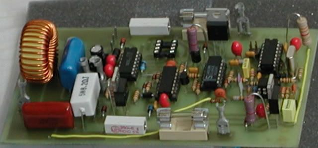
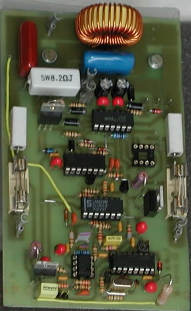
Here are some pic
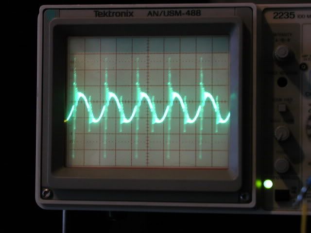
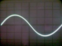
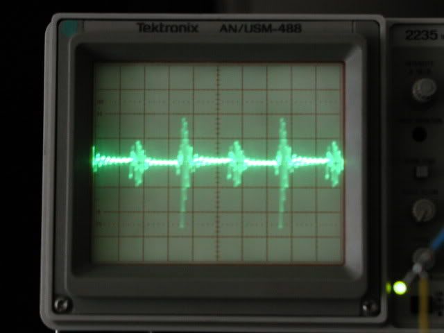
This one is from output sine wave 250kHz, 0.5v/div, spikes because of poor decopling cap cross +/-Vcc, maybe aslo because of too big inductor, don't know the value of it.
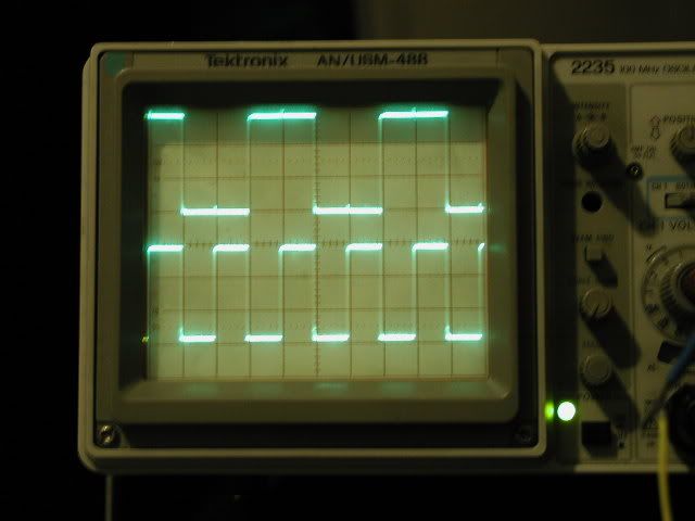
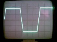
And this one is from output also near clipping. 10v/div, with input on 1v/div (upper one). Amps supply is from car smps at +/-30v
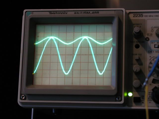
Have no problems going into max clipping, so that output is squere wave
What do you think?
Here are some pic
This one is from output sine wave 250kHz, 0.5v/div, spikes because of poor decopling cap cross +/-Vcc, maybe aslo because of too big inductor, don't know the value of it.
And this one is from output also near clipping. 10v/div, with input on 1v/div (upper one). Amps supply is from car smps at +/-30v
Have no problems going into max clipping, so that output is squere wave
What do you think?
Hi luka !
Nice results...
The spikes you see on 250khz sine wave are due to dead time i think...
try to make it longer and you'll see these spikes disappear...
50Vpp at clipping that's it ?
so 78Wrms under 4 ohms load...
I got no problem till 60Vp so 450WRMS under 4 ohms...
at 60Vp got some ringing at the top of the sine wave.
i pushed it to 144Vpp so 650WRMS
do you implement overload protection onboard ?
Hi
Not jet. Tomorrow. When I said near clipping I did mean that one side of signal was near, not both (problem in generator), so there cant be normal clipping on top and bottom of signal. I should say that at this point I didn't had load connected. Reason for that is that I don't have right equipment (supply for amp). So for now I am limited to +/-30v one, but still with some mod in feedback I will raise it to +/-50v.
Dead time? I will look at this. But I don't think there in any throughshoots, because there is low consumption.
I have looked at this just now and I see 3A spikes on series resistors. This is indicating that there are throughshoots. How much should I increase resistors? They are 100 now.

- Status
- This old topic is closed. If you want to reopen this topic, contact a moderator using the "Report Post" button.
- Home
- Amplifiers
- Class D
- D AMP is back !!!