The spacing, d , is not actually involved in defining the obtainable force per unit area.
That is just a part of the truth.")
The formulas clearly show a anti-proportionality of attainable Forces to the distance d. It also shows that You need to increase the voltages to obtain the same Force-values when You increase d.
Since we must(!) stay below the maximum force which is defined by the flashover treshold, only the range below Fmax is of interest and here the 1/d proportionality applies. In other words. As long as the panel doesn´t flashover a decrease in spacing d will result in higher Force, hence higher SPL, if we keep Vpol and Vsig unaltered. On the other hand, if we increase d we need to increase Vpol and Vsig to rearrange for the same Force again. The choice of d should then only depend on the excursion needs. So, if we have chosen a value for d that meets the excursion demands, any further increase in d is not only obsolete, but actually counter productive, in that the required higher voltages (and associated with it increased Power) mean increased effort, inferior signal quality, less safety and speeded aging.
As far as I can tell reading your reply, your statements agree with my conclusion. The maximum obtainable force per unit area is defined by the flashover threshold for air, not the spacing d. As you say, if you increase d you need to increase Vsig and Vpol to get the same Force. But you can without risking flashover because the spacing is larger by the same ratio that the voltages need to be increased.
Choose the spacing required for the desired LF excursion and this defines the required Vpol and Vsig for maximum obtainable force. The maximum obtainable force would be the same no matter what spacing you chose. Only the Vsig & Vpol required to obtain it would be different.
Two common reasons people use transformers resulting in less than optimum Vsig.2) If your transformer generates less than optimum stator voltages, turning up your bias beyond the optimum Vpol value will result in higher sensitivity and increased maximum SPL.
This is indeed correct, but who would design so in first place?
If I were to design a F1 car, I surely wouldn´t opt for a 125ccm Motorbike engine, but a 3.000ccm racing engine. Whywhen You can
?
A tranny that is incabable of supplying the optimal Vsig is simply not the right tranny for that certain application.
1) They choose to use cheap or readily available step-up transformers. Not everybody has the ability to design or $$$ to purchase an optimum transformer.
2) They are unable to achieve the bandwidth they want with a higher step-up ratio. Either limiting the HF due to parastics of leakage inductance and winding capacitance, or limiting the LF due to core saturation.
I'd say hard to keep panels adequately stiff, especially as the surface dimensions grow. So there are hard limits a builder faces unless they can weld steel braces. But it is not too hard to increment voltages upwards with bigger spacing, if you have a solid mechanical base. With the high voltages around ESLs, I bet few people are rapping their knuckles on the panels or feeling them for vibration while playing - that's the way we always do it with speaker boxes. Ever wonder how badly the flimsy Quad panels rattle? Or sheets of perforated steel that everybody uses? You could trust your life to the strength of Dayton-Wright panels, by contrast. Why are we nutty about the solidity of speaker boxes but pay minimum attention to the rigidity of ESL panels?
Again you mention it is "not too hard to increment the voltages upward with bigger spacing".
Actually, in practice, it is.
Sure, there is not much difficulty in generating higher polarizing voltages. But, that is only have the equation. The other is the need for higher signal voltages. In my experience it is difficult to ramp up the signal voltage and retain the same upper and lower bandwidth. Now if you are only planning on using your ESL over a restricted bandwidth, such as a woofer and/or midrange, then generating higher signal voltages isn't as big a problem.
I totally agree about the necessity to build structurally sound ESL panels. I spend a great deal of effort ensuring they do not emit any undesirable vibrations. As has been mentioned elsewhere, it is generally quite embarrassing to apply a high level slow sine wave sweep to most ESLs, both DIY & professionally manufactured. It is a challenge as the stators need to be as acoustically transparent as possible, and some people prefer optically transparent as well.
Hunt's research did show exponential forces for constant voltage ESLs.Yes, going big in any dimension means proportionally and absolutely less diaphragm displacement - but easier to achieve with spacing. Which, I am pretty sure, means better performance. The mathematics of ESL forces are not pretty, as best as I can remember Hunt. That's why big-voltage bias HAD to be introduced, eh. I think as soon as you start serious movement, you get into exponential instead of linear forces.
But, must people build constant charge ESLs so that the forces are linear thru out the whole stroke right up until the diaphragm hits the stators. Refer to the Force equations Calvin and I have been posting. Force is a linear function of Vpol & Vsig. Position of the diaphragm in the gap is nowhere to be found in the dynamic portion of the equation. We didn't mention it, and probably should have, that these equations are applicable to constant charge ESLs only.
OK... but then with the best old step-up transformers you can get your hands on, you make biggish spacing, largish bias voltage, and then the old step-up transformer will be working at its most efficient, however limited that may be by your circumstances.
Is that wrong?
No. Nothing "wrong" with that per se.
But your efficiency and maximum obtainable SPL will be more restricted than if you reduced the spacing and bias voltage to match the output capability of the step-up transformer.
Back to the armchair. There are very few things you have any clarity about before you build. You don't want to have more signal voltage than you can use. So you err on the side of spacing. You can readily get the bias voltage adjustable and potentially too high (before adjustment down). You build. Then you see how well your signal drives your panels.
With many unknowns (well, known precisely as models on paper, of course), the process will be iterative. Your bias is adjustable so that's helpful. So what don't you want to iterate? You sure don't want to iterate building panels. That leaves the signal drive to be changed upwards to meet the potential of your panels... assuming you left room (spacing) for upwards potentials.
Personal history: I've fooled with ESL over the years, but never with panel building. I have a hoard of Dayton-Wright panels (around 40 of them) as well as a complete speaker pair (8 identical panels per speaker). Lucky me, all I had to do with get bigger amps and bits of EQ to drive the collection of reversed tube output transformers I had collected. For about 20 years, I used my direct drive Sanders-like 2400 v B+ amp. Perhaps I am just promoting the kind of process I've gone through, starting with fine panels and adjusting the electronics to them.
Last edited:
Hi,
If You look especially into older ESL Models -even of the big names- You´ll discover cheap transformers, that´s quality ranges don´t exceed or are even below that of nowadays standard E/I-core power trannies, let alone toroids.
Using panels with smallish d/s, hence low voltage demands and hence low U-value demands, generates the possibility to use less expensive but high quality Off-the-shelf trannies that outperform the old stuff quite easily. To the contrary it are the small production numbers, large d/s, high voltage, high-U fraction of trannies which need spezialized and complicated winding that costs loads of bucks.
Don´t be surprised, but I don´t share this opinion.
There´s no reason why an old transformer should be capable of better performance than a new one or easier to get Your hands on. There´s also no reason why the best old transformers should only be of high-U value. It still applies that the lower the transformation factor could be the better the results will be. The best transformer is the one that matches the impedance values best and allows for sufficient bandwidth.
There are to my knowledge only few companies that used very high U-values of >>100 in their StepUps over the complete working range.
Dayton was one, Quad another. Acoustat and Audiostatic used high U values just over a restricted range in bass and lower mids.
The Daytons needed high-U-trannies because of the large d/s spacing which led to a low capacitance, hence highish impedance level of the panels. The Quads 57 needed a lot of U to drive the resistors that should lead to a current drive of the panels. Because of their d/s being reasonably small the Quads needed much less U when voltage driven.
The same basically applies to the Quad 63 and its heirs. Its smallish d/s needed much lower values of U if it were voltage driven and if they omitted with the crude delay line and used resistor segmentation instead (the difference would be that the impedance value and as such the need for high U-trannies would decrease considerably).
To me it seems that the problem You Ben and many others experience is, that You rather only think in voltage terms instead of thinking in impedance terms first and then look at the voltage levels.
If You want to build a panel all dimensions can be calcualted for the specced dynamic range and bandwidth. The only real variable and unknown factor is how much ´safety-margin´ in d/s You add to cater for dimensional aberrations of the stators, spacers and the x-offset from the polarizing voltage. This is indeed a factor of experience, but be sure its much less than 100% of the d/s for a decent panel ;-)
So even with a FR-Panel of reasonbaly proportioned size You should be able to get away with 3mm of d/s or less. If its more You should closely check the design again. ;-)
jauu
Calvin
The optimum transformer will be that which matches the panel´s demands best. That is not necessarily correlated to the attaced price tag and certainly no question of old or new stuff. It´s only a question of impedance matching and bandwidth.1) They choose to use cheap or readily available step-up transformers. Not everybody has the ability to design or $$$ to purchase an optimum transformer.
If You look especially into older ESL Models -even of the big names- You´ll discover cheap transformers, that´s quality ranges don´t exceed or are even below that of nowadays standard E/I-core power trannies, let alone toroids.
Using panels with smallish d/s, hence low voltage demands and hence low U-value demands, generates the possibility to use less expensive but high quality Off-the-shelf trannies that outperform the old stuff quite easily. To the contrary it are the small production numbers, large d/s, high voltage, high-U fraction of trannies which need spezialized and complicated winding that costs loads of bucks.
OK... but then with the best old step-up transformers you can get your hands on, you make biggish spacing, largish bias voltage, and then the old step-up transformer will be working at its most efficient, however limited that may be by your circumstances.
Don´t be surprised, but I don´t share this opinion.
There´s no reason why an old transformer should be capable of better performance than a new one or easier to get Your hands on. There´s also no reason why the best old transformers should only be of high-U value. It still applies that the lower the transformation factor could be the better the results will be. The best transformer is the one that matches the impedance values best and allows for sufficient bandwidth.
There are to my knowledge only few companies that used very high U-values of >>100 in their StepUps over the complete working range.
Dayton was one, Quad another. Acoustat and Audiostatic used high U values just over a restricted range in bass and lower mids.
The Daytons needed high-U-trannies because of the large d/s spacing which led to a low capacitance, hence highish impedance level of the panels. The Quads 57 needed a lot of U to drive the resistors that should lead to a current drive of the panels. Because of their d/s being reasonably small the Quads needed much less U when voltage driven.
The same basically applies to the Quad 63 and its heirs. Its smallish d/s needed much lower values of U if it were voltage driven and if they omitted with the crude delay line and used resistor segmentation instead (the difference would be that the impedance value and as such the need for high U-trannies would decrease considerably).
To me it seems that the problem You Ben and many others experience is, that You rather only think in voltage terms instead of thinking in impedance terms first and then look at the voltage levels.
If You want to build a panel all dimensions can be calcualted for the specced dynamic range and bandwidth. The only real variable and unknown factor is how much ´safety-margin´ in d/s You add to cater for dimensional aberrations of the stators, spacers and the x-offset from the polarizing voltage. This is indeed a factor of experience, but be sure its much less than 100% of the d/s for a decent panel ;-)
So even with a FR-Panel of reasonbaly proportioned size You should be able to get away with 3mm of d/s or less. If its more You should closely check the design again. ;-)
jauu
Calvin
Last edited:
I'll try this gain, please point me in the right direction.
Calculating current, impedance, driving voltages and the driving force on the diaphragm I understad somewhat but I can't make the leap to SPL?
Naturally I understand that more Force will lead to higher sound levels but I still can't make the mathematical connection to SPL?
Oh, I almost forgot... there's one thing in the force equation that puzzles me.
The X factor, i.e. the diaphragm offset. How do you attain the diaphragm offset? (I assume this is the bowing of the diaphragm because of the polarizing voltage?)
Last edited:
Back here on Planet Earth, most of us are pretty clueless about what to expect from a step-up transformer, even in the highly unlikely event we had a bunch of parameters for that transformer. As Markus suggests.
The widespread advice at DIYaudio about finding some "old" (meaning here, "off the shelf") toroid power transformer... just how does that connect to sophisticated talk (some would say, gobbeldygook) about cores and U (I don't know what "U" is)? New or old, many of us work with what we find at the local electronic surplus store or can scrounge from an old tube amp, etc. Only manufacturers can (or need to) calculate the fine-points of transformers they order by the carton... after a lot of practical experimentation to see if engineering theory bears much relation to performance.
And to assess our progress, we deal with voltage because we can measure voltage.
With wider spacing, as Calvin points out, the panels become more invisible as a load as their capacitance decreases.
Footnote: if the folks at Acoustat chose the dinky-looking transformer that Calvin disparages (as well as many other vendors), I guess that was their best judgment that it was a reasonable match to their system and not because they really wanted to introduce an especially weak link. Dayton-Wright's 18kg transformer aside, these often do look shoddy, like most hidden-away transformers do.
From the lack of replies on this subject, you probably have gathered that the answer is:I'll try this gain, please point me in the right direction.
Calculating current, impedance, driving voltages and the driving force on the diaphragm I understad somewhat but I can't make the leap to SPL?
Naturally I understand that more Force will lead to higher sound levels but I still can't make the mathematical connection to SPL?
“It’s complicated”
I will try to give a brief summary of what is involved as I understand it from reading the book Acoustics by Beranek.
The standard method used to calculate SPL from known driving Forces is to create an electrical circuit that is analogous to the mechanical and acoustic properties of the transducer you want to analyze. Force is replaced by voltage, mass by inductance, compliance by capacitance, damping by resistance. The actual values of the components can be calculated based on physical properties. Acoustic output is then proportional to current thru the real part of the radiation impedance.
For dynamic drivers some simplifications can be made because the moving mass of the driver dominates the other components in the circuit. For ESLs this is not the case. The dominate circuit components are those representing the radiation impedance which, as Calvin has pointed out, is a complex function of diaphragm size and shape which has no closed form solution. Also, this type of modeling does not take into account directivity as you go up in frequency and the wavelength gets smaller than the size of the ESL diaphragm.
For reference, I had posted some plots of radiation impedance for some diaphragm shapes in another thread you had started.
http://www.diyaudio.com/forums/planars-exotics/175067-no0b-esl-size-question.html#post2327517
“The easy way”
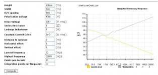
In post#8 of this thread kavermei already posted a link to an SPL calculator for ESLs. Some people questioned its validity, but I have found that when used with proper inputs and understanding it’s limitations it gives accurate results. It is based on “The Walker Equation” that Peter Walker developed using something called the reciprocity principle which completely side-steps all the complications mentioned above. If interested, the complete derivation can be found in Section 3.3.2 of the Baxandall paper.
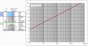
As a sanity check of the online calculator, I compared the results for a 5cm wide line source with those calculated using the line source spreadsheet I had posted here:
http://www.diyaudio.com/forums/planars-exotics/48120-experiences-esl-directivity-9.html#post2218526
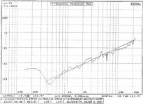
See Attachment 1) & 2) for comparison. The agreement is quite good, both in SPL magnitude and in the expected 3dB/octave slope for an ESL line source. I know several posters mentioned never having seen measurements like this before. I have seen measurements like this many times. I am away from home on business right now, but happen to have a print out of a measurement I took last year of a 2" wide ESL line source. I have scanned it in as Attachment 3). The 3dB/octave slope is evident. The SPL magnitude is not shown in the measurement, but it did agreed within 2dB of the calculated values. I consider this pretty good agreement considering that the voltage loss in the stator insulation is not accounted for in the Walker Equation.
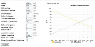
If you are interested in what the standard sensitivity would be for 2.83Vrms(1Watt/8ohm) change the Drive Voltage to 2.83 x (step-up ratio). See Attachment 4) for the SPL of the ESL line source from Attachment 1) driven with 300Vrms. Obviously the response still has the 3dB/octave slope which you will need to equalize out. So, the SPL “rating” for 2.83Vrms input will depend on how low you want to crossover your ESL. For example, if you wanted to cross over ~600Hz, your dB/2.83V = 70dB. This low value gives you an idea why it is generally advisable to make your ESL as large as possible. Each time you double the width of the line source, you increase this value by 6dB. Of course making your ESL wide reduces the dispersion of high frequencies which is generally not a desirable thing, although some people like it.
I hope this quick summary helped rather than adding confusion.
Attachments
I have been to the library and got myself some "light" reading.
Loudspeaker and Headphone handbook + an AES article.
It'll probably be a little while before I've managed to process all the information but I'm working on it.
Your summation did indeed clear somethig up for me. I had asked myself that exact question which you answer. Bases on the 2.83Vrms reference, depending on the step-up, what spl can one expect at what XO-frequency.
Reading the sim/curve that way helps a lot.
Looking at it like a regular frequency plot it's just confusing since I've never seen a speaker behaving that way.
It does make me wonder exactly what I'm seing in this grapgh and what makes it different from the spl plots I'm used to seeing. (The "flat" ones...)
It does make me wonder exactly what I'm seing in this grapgh and what makes it different from the spl plots I'm used to seeing. (The "flat" ones...)
The measurement I posted was taken using a HV reference probe to remove any influence of amplifier and/or transformer response.
The far-field native response of all unbaffled dipole ESLs is a rising response with increasing frequency. (+6dB/octave for point source, +3dB/octave for line source)
Anytime you see a flat ESL response, there is some equalization involved(intentional or not):
- curved ESLs spread out the highs rather than focus them flattening the high frequency response
- mass of diaphragm can flatten the HF response
- mass of air in stator holes can flatten the HF response
- any series resistance in primary or secondary circuit changes constant voltage drive to constant current and flattens the response
- any segmentation and ladder resistor network adds area with decreasing frequency to flatten the response
- leakage inductance of transformer flattens HF response
- boosting of LF response with underdamped HP filters can flatten the mid and LF response
- baffling around the edges of the ESL can flatten the mid and LF response
Also, many times measurements are not taken far enough away to be in the far-field.
As was mentioned earlier in this thread, near field response of ESL is flat.
It may help to think of the SPL response from the simulation as the maximum possible output .vs. frequency.
The desired response will be the loudest flat line you can fit underneath this maximum curve dependent on your crossover frequency.
Last edited:
Bolserst, those are very interesting measurements, and remarkably close to the Walker equation. Thanks!
Markus, a crucial thing here is that these measurements were made without accounting for the influence of the transformer -- this might explain why you've not seen these frequency responses before.
Thankfully, an ESL panel has a rising frequency response! Many of the practicalities bolserst lists in the previous post tend to have some HF loss and therefore (at least partially) equalize it out. Imagine if ESL panels had a 3dB/oct *drop* in response, we would have been in a lot more trouble.
Kenneth
So, we have designed wonderful panels that are close to theory when measured in the carefully defined manner defined so well above.
We mount them on a board or frame of some sort, stand them at some distance from the back wall, they form some angle between them and the listener, sit at some distance from them, in a room of some asymmetry, which has some degree of absorption.... and then we begin trying to make them sound right because there is SOME big differences between design and practice at this point in time caused by some of these factors.
Careful, theory-based design is important. It makes a good starting point for tuning systems when they get to your music room.
Of course it may be asked, if you need to do substantial re-tuning when the speakers get to your music room, how deep into theory-based design do you need to go?
So we find Markus still hanging around the library instead of in the workshop.
Last edited:
The Quads 57 needed a lot of U to drive the resistors that should lead to a current drive of the panels. Because of their d/s being reasonably small the Quads needed much less U when voltage driven.
The same basically applies to the Quad 63 and its heirs. Its smallish d/s needed much lower values of U if it were voltage driven and if they omitted with the crude delay line and used resistor segmentation instead (the difference would be that the impedance value and as such the need for high U-trannies would decrease considerably).
Hell Calvin,
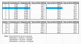
I have not had the chance to inspect or measure a Quad 63. But, from the circuit diaphragm and details mentioned in Baxandall’s ESL paper I am confused by your comment about the step-up ratio(U) of the transformers being unnecessarily high because of the delay lines. The D/S spacing is 2.5mm. The step-up ratio(U) is 245 and Vpol = 5.25kV. This seems to fit in pretty well with the optimum values calculated by Baxandall assuming a breakdown voltage for dry air of Emax = 4kV/mm. See attached table which summarizes required optimum Vpol & Vsig for different D/S spacing. I also added columns to show the required transformer step-up ratio(U) required to obtain Vsig for amplifier outputs of 50W/8ohm, 100W/8ohm, & 200W/8ohm.
I highlight the Quad 63 values in blue. Note that it was designed for a maximum recommended input voltage of 40Vpeak = 28.3Vrms = 100W/8ohm.
Looking at this table you can also get a feel for how quickly Vsig and setup-up ratio(U) quickly gets out of hand if D/S spacing larger than a few mm is used.
I understand that if you removed the delay lines and ladder resistors the panel would be louder in the midrange, but those components are used to EQ the response flat. So, I guess you could use a smaller step-up ratio(U) transformer to get the same midrange SPL level if the delay lines and ladder resistors were removed. But, the high step-up ratio(U) is needed to provide the maximum possible SPL at low frequencies(<100Hz) where the delay lines and resistors aren’t really influencing the response. At least that is the way I understand it.
Attachments
Last edited:
Hi,
the breakdown voltage of air is at best 2kV/mm, a safe value beeing ~1.5kV/mm, which roughly corresponds to 1kVrms/mm of signal voltage.
The problem is that the the driving source only sees a small capacitance through the delay line, which is just a fraction of the complete panel area. So the impedance values are high and as such the transformation factor alas voltage demand must be high. Add to this the losses of the series resistors that shall allow for current drive conditions and You end up with the ridicolously high U of 1:270 of the ESL63. Still though the current-drive condition doesn´t apply in the low bass, since this required such extreme high resistor values that the voltage demand and transformation-factor would result in impractical values. The only thing that saves the day here is the high-Q resonance of the panel. Quad simply says...if the resonance is there anyway and we can´t get away with it, let´s use it. So in the low bass region the panel works under lossy voltage drive conditions (lossy, because the resistors are still in the signal-path). The associated falling amplitude response with decreasing frequency is then countered by the high Q of the resonance to give a quite linear response. Over all the whole is marvellously engineered ..... the only pity beeing, that its concept starts from compromised premises.
The flaws of the concept as I see it, are:
- to neglect the fact that a 1:270 transformation factor does not com without serious drawbacks. A transformer with lower transformation factor will always measure and sound better.
- to assume that a point source is advantagous in real room situation
- using a delay line instead of a chain of simple segmenting resistors, which eq the panel and lead to a similar distribution character but without the drawbacks of the delay line.
- driving fullrange, which discludes the current-drive condition over the full bandwidth
- driving fullrange and thereby accepting and fudging around with a high-Q resonance, which nobody would accept as a high quality solution if dynamic bass drivers were to use. The high-Q audibly recognizable in that it leads to a distinct soft-noted bass.
- small sized panel segments, series resistors, high-Q resonance at a low frequency and high-U transformer spoil the dynamic range.
Using simple resistor segmenting instead, the driving source sees the whole panel area, successively decreasing with frequency. So impedance values are considerably smaller, hence the voltage demand and transformation factor can be lower. With a panel of the ESL63´s dimensions one could expect values of app. 1:100. Since the first segmenting resistor feeds into the second segment the trannie´s (or source´s) drive voltage feeds directly into the first segment, hence no losses or increased voltage demand. The segmenting resistors serve two purposes...to eq the panel´s frequency response and to shape its distribution character. So it serves the same aims as the delay line, but without suffering from thats serious compromises.
jauu
Calvin
A few odd thoughts:
Any transformer seems a weak link in an ESL system (compared to a direct drive amp). But my guess is that Quad was trying to get their speakers to work with low power amps and so may have needed the high turns ratio units that Calvin indicates. That seems an odd goal today and not an inherent limitation of their highly successful segmentation design.
Yes, trafficking in resonances (like the multi-resonant tapped horn) seems low-fidelity. But the resonances you get making bass by shaking large hunk of cardboard (shaped like a cone) is altogether of a different order as shaking mylar film. Again, funny to try to get serious bass from ESLs (large Dayton-Wrights in sulfur hexafluride gas, excepted), so this is another will-of-the-wisp Quad goal that seems funny today.
I guess I prefer the "look at me" show-off quality of Martin Logans to the refined full ESL compass of the Quads. But no question that a Quad owner has a fabulous speaker pair to listen to.
We ESL fans gladly accept various shortcomings that come with ESL designs because we are so attached to the crystal clarity.
In the midst of this discussion I have a question about the idea that a fullrange ESL has to be compromised in the bass. I know and understand Ben what your saying from a layman perspective, however what explains how I'm getting great bass weight and dynamics from a single Acoustat panel wired into two stock 121A non-medallion interfaces, with the bass tap on the transformer wired for Model 3? Meaning that the bass transformer is set for 3 panels of Acoustat not one (there are multiple taps available for different panel numbers). This set up is in a modest sized living room (not small not large) and that the panels I have are totally undressed with no framing of any kind. They are propped up on sticks of wood a few feet (maybe 32-34 inches) from the back wall and 5 to 7 feet from side walls. They are not the most dynamic speakers I've ever heard but the smack of drums and weight of kick drum and the sound of both electric and acoustic upright bass instruments is totally a believable. This all coming from a single 9" x 45" Acoustat panel that is close to 30 years old being driven by a high current Harman Kardon design from the mid 90's. Really a head shaker in terms of resolution, dynamics, coherence, and the sweetest mids and highs you coulsd ever want. They are the kindest speakers to my ears I've ever had yet all the details are perfect. Every nuance is there. Yes I can drive them enough to smack the mylar right into the stators. Yes the charge will migrate if I shake them up a bit too much and volume will suffer momentarily while the panel charges even up. I can even get them to arc but they really have real bass into the 30 hz range. In my mind if an open baffle servo powered dynamic sub were introduced into the contiguous acoustic space comprising the front and rear air space of the Acoustat driver, then there would be an acoustic "helper". This dynamic sub operating 80 or lower would couple with the mylar acoustically pressurizing it and thus possibly limit the excursion of the mylar with large bass transients. The sub would necessarily have to be open baffle to fully couple with the air space. Why not do a larger panel than Acoustat 9"x 45"?
I have never heard the bass resonance or ringing of the mylar diaphragm. Is this a considerable problem with large unsegmented full range panels? Any thoughts?
I have never heard the bass resonance or ringing of the mylar diaphragm. Is this a considerable problem with large unsegmented full range panels? Any thoughts?
- Status
- This old topic is closed. If you want to reopen this topic, contact a moderator using the "Report Post" button.
- Home
- Loudspeakers
- Planars & Exotics
- Current vs voltage drive ESL?