Quick question: have you confirmed the bass extension with a mic? Where does it taper off?
With a free computer oscilloscope with a real-time spectrum analyzer program, you can see exactly what is present and what is not, even just playing an organ recording.
Quite amazing how little difference it makes when I turn off my bass (110 Hz crossover). No question I can tell the difference on music with lots of bass content... usually. But not a big difference.
Ben I assume this is to me. I just did a 35-200 hz sine tone sweep and there is solid bass at 37-45 hz. As audible and tactile as it needs to be. Deep and strong. I can arc the panels with sine tones played too loud. Some panels worse than other due to conductive dirt buildup on the wire insulation and stator parts. This does not happen on music but with very rare exception with heavy bass content that is mostly overdone in the recording. Other than that the bass is being produced in the critical mid 30's with the strength it needs for musical realism. It is not flat but no speaker is flat in room at frequencies like that. The home environment is hard to sterilize from peaks and dropouts in the bass and lower bass. You just got to set up the room right and you get luckier sometimes and sometimes not so lucky. Feeling is that it would be rather good to keep the full range panel "producing" low bass but at a roll off that is natural and to normalize the detrimental affects that bass overkill can have on a full range ESL's excursion limits. I seriously am toying with finding an "acoustic" solution such as a powerful fast open baffle sub that augments 80hz or even 60 hz and below. And to let the panel go as low as it wants to but have a natural attenuation at strong bass frequencies. I have never found the idea of a dynamic boxed subwoofer operating into the 100hz range and the panel cut off from those frequencies at 100Hz to be a perfect solution. Sanders pulls off a feat but I've never heard his speakers so I cant say much about it. I've heard Martin Logan of all kinds and they sound detached from the dynamic subs on them. Also sound thin in the meaty part of the mid bass where some of the body of the lower midrange is fleshed out. ML is not my kind of speaker. The full range Acoustat does a lot for me in these areas. I'm in experimental mode and there are sonic drawbacks. I will say that the head in the vice effect is all but gone with proper toe-in and use of the wall reflection is helping that. But the nine inch width of the bare panel and no obstructions behind the speakers but plenty of diffusion from objects like drapes windows furnishings helps. Off axis the most notable thing is loss of highs and the sound stage changes. But not nearly like when you have multiple panels side by side. On that note the 3 panel wide speaker (Model3) actually has the "balls" to shake the room. So more panels and more surface gets the bass fully coming in at the deepest registers but the purity of the sound throughout the room is compromised as is the size of the sweet spot. I'm just amazed that the single bare Acoustat panel is making believable bass down into the 30s. Very listenable. Accurate in terms of flat response is another matter altogether. Home listening is ragged response all the time I've ever listened to full audible spectrum sweep tones. It's a damned rollercoaster ride for the ears if you know what I mean. But then you put on some tunes and its heavenly.
Doesn't sound healthy for the panels to flap. Time for the hair dryer treatment?
Although I would not give me a credibility rating over 5 on a 100 point scale for the following, about annually I would use the hair dryer on panels in order to drive off moisture and shrink the film. Don't do this unless others on the forum support the rationale and doing the procedure.
Weak bass is one of those things ESL die-hards live with if they think no cone can complement their panels. Not me - I don't think there's any obstacle to pasting-on a sub anywhere south of, say 150 Hz, and a single one at that. Waves is waves and talk about dispersion, directivity, etc. at those frequencies sometimes verges on the apocryphal.
The mylar is plenty tight. I have enough power to touch them to the stators. It is of course distorted by that time. Static forces are pretty powerful and the diaphragm only has about 1.5mm of travel each way stator to stator. The panels are as healthy as they come. I hope to build some from scratch soon.
Any further thoughts on some of the ideas I mentioned? Such as the OB dynamic sub to acoustically couple with the ESL panel.
Any further thoughts on some of the ideas I mentioned? Such as the OB dynamic sub to acoustically couple with the ESL panel.
Last edited:
Calvin,
Thanks for taking the time to put in words your technical critic of the QUAD 63.
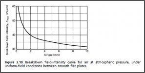
For reference I attached the plot of breakdown voltage vs airgap for parallel plates that Baxandall used which was taken from “Gaseous Electrical Conductors”, WHEATCROFT, E L E, Clarendon Press, Oxford (1938). If interested, I also attached a more recent paper on the subject discussing trends of breakdown voltage with electrode size and spacing. This paper specifies a value of 3kV/mm for breakdown between parallel plate.
FWIW, I tested the breakdown voltage of air for my wire stators and determined breakdown at 3.5kV/mm for 1.6mm(1/16”) spacing and 3.0kV/mm for 3.2mm(1/8”) spacing.
Thanks for taking the time to put in words your technical critic of the QUAD 63.
I certainly would not argue with your recommendation of 2kV/mm breakdown value for ESLs built with perforated sheet metal stators. The breakdown voltage is dependent on the geometry and separation distance of the electrodes. The sharp edges around stator holes will promote conduction and arcing at lower voltages than between smooth wires or plates. Evidently QUAD shared your concern as they did incorporate an arc protection circuit in the ESL63. Baxandall does not mention if the 4kV/mm value that the QUAD 63 design was based on was experimentally verified for their stator construction/geometry. Perhaps they would have been better off basing their design on a lower value of breakdown voltage than 4kV/mm.the breakdown voltage of air is at best 2kV/mm, a safe value being ~1.5kV/mm, which roughly corresponds to 1kVrms/mm of signal voltage.
For reference I attached the plot of breakdown voltage vs airgap for parallel plates that Baxandall used which was taken from “Gaseous Electrical Conductors”, WHEATCROFT, E L E, Clarendon Press, Oxford (1938). If interested, I also attached a more recent paper on the subject discussing trends of breakdown voltage with electrode size and spacing. This paper specifies a value of 3kV/mm for breakdown between parallel plate.
FWIW, I tested the breakdown voltage of air for my wire stators and determined breakdown at 3.5kV/mm for 1.6mm(1/16”) spacing and 3.0kV/mm for 3.2mm(1/8”) spacing.
I still am not convinced that the delay lines are what is driving the need for the high step-up ratio. I think that it is really the desired bandwidth and voltage sensitivity(SPL for given voltage input). They wanted to be able to drive the speaker to peak output with a 100W/8ohm amplifier. If you took the QUAD 63 panel and replaced the delay lines with ladder resistor that EQ the response flat to the same bandwidth, I think the same step-up ratio(U) would be needed to achieve the same voltage sensitivity. This is because the only time the whole panel sees the full voltage output of the transformers is at low frequencies(<100Hz) where the delay line inductors and ladder resistors pretty much look like short circuits compared to the capacitance of the individual panel sections. So, it doesn’t really matter which you used to EQ the high frequencies flat. The output at low frequencies is not affected by them. Perhaps if I ever get the opportunity to measure a QUAD 63 I would change my mind.Using simple resistor segmenting instead, the driving source sees the whole panel area, successively decreasing with frequency. So impedance values are considerably smaller, hence the voltage demand and transformation factor can be lower. With a panel of the ESL63´s dimensions one could expect values of app. 1:100. Since the first segmenting resistor feeds into the second segment the trannie´s (or source´s) drive voltage feeds directly into the first segment, hence no losses or increased voltage demand. The segmenting resistors serve two purposes...to eq the panel´s frequency response and to shape its distribution character. So it serves the same aims as the delay line, but without suffering from thats serious compromises.
Attachments
Last edited:
Since this thread is about current drive, I will add that Baxandall mentions in Section 3.3.2 that if the stators are fed from a current source the linear negative stiffness term drops out of the Force equation. This means that varying the polarizing voltage would have no affect on the fundamental resonance of a current source driven ESL. I haven’t verified this experimentally yet, but plan to in the near future.
Well, I finally got around to taking some measurements of how the negative stiffness term affects Fs(fundamental resonance) of an ESL when driven constant voltage source or constant current source. The results match theory quite well, and confirm Baxandall's statement that the negative stiffness term drops out of the constant charge ESL Force equation if constant current drive is used.
I took NF(near field) measurements to determine Fs of diaphragm for several bias voltages levels between 870Vdc & 5010Vdc.
Attachment 1)
Shows the NF response for the min and max voltages with ESL driven by VS(voltage source) and CS(current source). I didn't have a current source amplifier on hand, but simulated one by putting 50Meg resistors in series with each stator. I must admit a was a bit skeptical that Fs would be different for the VS and CS case, but they clearly are. I also added a dotted trend line along the expected -6dB slope of the CS curve.
Attachment 2)
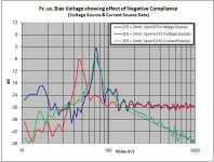
Shows the trend of Fs with Vpol for both VS and CS cases. I also added in a curve showing what trend theory would predict for the VS case. So, you can see that one clear advantage of CS drive for an ESL is that Fs is essentially unaffected by the value of Vbias.
Taking a look at the negative stiffness term of the force equation....
F= Eps0*A*2*Vpol²*x/d³
You can see that it increases as square of Vpol, but decreases as cube of D/S spacing.
So, for the same panel area and diaphragm tension, if you double the D/S spacing and double the Vpol value to obtain the same efficiency, the negative stiffness term will have less affect on Fs.
Attachment 3)
Adds in a theoretical Fs trend for the case of doubling the D/S spacing from 2mm to 4mm.
As you can see, Fs is much less affected by the value of Vpol.
This is a clear advantage of larger D/S spacing which I was unaware of.
However, It is probably unimportant for hybrid designs where smaller D/S spacing is most common.
Attachments
Nelson Pass' write-up examining "current" drive is instructive. While you can shake a cone driver in ways that kind of look like a flatter frequency compass on sustained notes using current drive, you are just piggy-backing on loosenesses and resonances.
Something akin is shown in these valuable and interesting measurements.
The higher polarizing voltage makes the mylar stiffer in the sense that it resonates at a lower frequency (on voltage drive) yet it clearly is dampening it better too, esp. below the resonance. That is a good virtue indeed.
I see no particular advantage in having "tractable" current drive which influences the mylar less as bias voltage changes. But I do see real advantages in increasing panel spacing and raising the voltage... with voltage drive.
BTW, as far as I can tell, neither Pass nor Elliot's write-up on high and negative impedance ("current") outputs are engaging the cone driver in the feedback loop. Certainly Elliot shows there's no advantage with simple current drive in the absence of feedback. But that is the missing key.
My amateur 2-cents.
Hi,
the breakdown voltage value is a value that depends on a lot of factors.
Among these are thickness of the probed material, the shape of the voltage curve over time (slew rate et al), time of applied voltage stress, atmospheric pressure, temperature of air and probed material, humidity, purity and surface finish of the probed material and some more. As such any value given is just a rule-of-thumb-value. There is a distribution of breakdown probabilities of which the values cited in literature are a mean value. In a specific case breakdown may not appear at all at those values, as well as it may already appear well below those values.
To be on the safe side one needs to subtract a safety margin.
The sources I found at Wiki and in actual University scripts speak of 2kV/mm to 3.3kV/mm, with higher values for lower thicknesses of the probed material (avalanche effect).
But maybe we are talking about different things alltogether?
If we include the stator insulating material into the breakdown value, we will of course achieve higher values than that for air alone. When for example one says that he uses a polarizing voltage of 10kV with a d/s of 2mm, You know that at least 6-7kV of it are dropped within the insulating layer which may feature a breakdown value of >20kV/mm with typical polymers. Unless one dispenses at all with insulation the true field strength in the airgap between stator and membrane is difficult to determine.
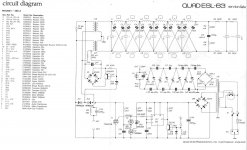
In the description of the ESL63 I made an error, because I wrote out of memory without looking at the circuit schematics before. The ESL 63 does not use a series resistor to maintain current drive. The Audio tranny drives directly into the first segment and into the delay line.
I still think though, that the delay line actually decouples the segments from each other, so that the amplifier only ´sees´ a small sized part of the panel, with its associated high impedance and the need for high transformation factors.
100W@8Ohms translates to 28Vrms of signal voltage, ~80Vpp.
With a U of around 1:260 this translates to a driving voltage of >20kVpp. The Membrane area of the quad is of considerable size and the airgap somewhere below 3mm (2.3 or 2.7mm if memory serves me right).
Just from a gut-feeling I expected cleary higher SPL-values if the membrane were driven over its entire area.
You did a nice job in veryfying the negative stiffness issue. I don´t share Your conclusions though.
You say for Attachment 2) that it´d be a clear advantage that the Fs keeps unaltered with CD. This might be the case if You´re design asks for an elevated Fs. But I´d say that on the other hand it could be regarded as an advantage that Fs drops under VD condition, since it allows for an increase in usable bandwidth.
You say for Attachment 3) that a high d/s affects Fs less than a smaller d/s. I think that the result is expectable and holds true for absolute values, but does it still hold true if we normalize the values? What happens if we redraw the curves using field strength as variable instead of the polarizing voltage? Wouldn´t the shape of the curves be very similar? In any case, what would be the practical advantage of a lower Fs- dependancy against d/s variation? Would a maybe advantage make up for the disadvantages of a higher d/s value?
jau
Calvin
the breakdown voltage value is a value that depends on a lot of factors.
Among these are thickness of the probed material, the shape of the voltage curve over time (slew rate et al), time of applied voltage stress, atmospheric pressure, temperature of air and probed material, humidity, purity and surface finish of the probed material and some more. As such any value given is just a rule-of-thumb-value. There is a distribution of breakdown probabilities of which the values cited in literature are a mean value. In a specific case breakdown may not appear at all at those values, as well as it may already appear well below those values.
To be on the safe side one needs to subtract a safety margin.
The sources I found at Wiki and in actual University scripts speak of 2kV/mm to 3.3kV/mm, with higher values for lower thicknesses of the probed material (avalanche effect).
But maybe we are talking about different things alltogether?
If we include the stator insulating material into the breakdown value, we will of course achieve higher values than that for air alone. When for example one says that he uses a polarizing voltage of 10kV with a d/s of 2mm, You know that at least 6-7kV of it are dropped within the insulating layer which may feature a breakdown value of >20kV/mm with typical polymers. Unless one dispenses at all with insulation the true field strength in the airgap between stator and membrane is difficult to determine.
In the description of the ESL63 I made an error, because I wrote out of memory without looking at the circuit schematics before. The ESL 63 does not use a series resistor to maintain current drive. The Audio tranny drives directly into the first segment and into the delay line.
I still think though, that the delay line actually decouples the segments from each other, so that the amplifier only ´sees´ a small sized part of the panel, with its associated high impedance and the need for high transformation factors.
100W@8Ohms translates to 28Vrms of signal voltage, ~80Vpp.
With a U of around 1:260 this translates to a driving voltage of >20kVpp. The Membrane area of the quad is of considerable size and the airgap somewhere below 3mm (2.3 or 2.7mm if memory serves me right).
Just from a gut-feeling I expected cleary higher SPL-values if the membrane were driven over its entire area.
You did a nice job in veryfying the negative stiffness issue. I don´t share Your conclusions though.
You say for Attachment 2) that it´d be a clear advantage that the Fs keeps unaltered with CD. This might be the case if You´re design asks for an elevated Fs. But I´d say that on the other hand it could be regarded as an advantage that Fs drops under VD condition, since it allows for an increase in usable bandwidth.
You say for Attachment 3) that a high d/s affects Fs less than a smaller d/s. I think that the result is expectable and holds true for absolute values, but does it still hold true if we normalize the values? What happens if we redraw the curves using field strength as variable instead of the polarizing voltage? Wouldn´t the shape of the curves be very similar? In any case, what would be the practical advantage of a lower Fs- dependancy against d/s variation? Would a maybe advantage make up for the disadvantages of a higher d/s value?
jau
Calvin
The higher polarizing voltage makes the mylar less stiff, not more stiff. This is why it resonates at a lower frequency.The higher polarizing voltage makes the mylar stiffer in the sense that it resonates at a lower frequency (on voltage drive) yet it clearly is dampening it better too, esp. below the resonance. That is a good virtue indeed.
Fs is proportional to sqrt(stiffness/mass)
The fact that the higher voltage curve is better damped(lower Q) is simply a function of the ratio of mass to stiffness. As with any mechanical resonating system, with mass held constant and stiffness reduced, the resonant frequency and Q are reduced. Alternatively, if you held stiffness constant, and added mass(by adding airload from large baffle extension around the ESL) the resonant frequency would go down, but Q would go up.
I believe I had mentioned this somewhere in the following thread as a reason I prefer lower diaphragm tensions rather than higher. All the diaphragm resonance modes are better damped with lower tension resulting in cleaner CSDs and less vibration of the stator frames.
http://www.diyaudio.com/forums/planars-exotics/168069-esls-have-bad-decay-plots.html
I didn’t mean to imply that is was a huge advantage, just a clearly measureable one. In general, it will be easier to deal with the resonant peak in the crossover(with a notch filter perhaps?) if it is fixed at a known frequency rather than changing with bias voltage. Like I said, for hybrids this may not be much of a concern since most people crossover over several octaves above Fs of the ESL. But, for a full range ESL where Fs may define the LF bandwidth limit, or it is less than an octave away from the LF bandwidth limit, it would be more of a concern.I see no particular advantage in having "tractable" current drive which influences the mylar less as bias voltage changes. But I do see real advantages in increasing panel spacing and raising the voltage... with voltage drive.
I have found no advantage in increasing panel spacing beyond what is required for diaphragm motion at LF. All it does is require higher Vpol and a transformer with a higher step-up ratio(U) and in the end you gain no improvement in efficiency, max SPL, or distortion. And, increasing the step-up ratio(U) while retaining the same bandwidth is not a trivial matter.
This is true. As the air in the gap starts to conduct and current flows, more and more of the polarizing voltage will be dropped across the insulation. Basically, the insulation is acting like a ballast resistor trying to keep the voltage gradient in the air gap below breakdown. To avoid this behavior from clouding my measurements, I ran my breakdown tests using uninsulated wires with same diameter as the OD of the insulated wires I planned to use.If we include the stator insulating material into the breakdown value, we will of course achieve higher values than that for air alone. When for example one says that he uses a polarizing voltage of 10kV with a d/s of 2mm, You know that at least 6-7kV of it are dropped within the insulating layer which may feature a breakdown value of >20kV/mm with typical polymers. Unless one dispenses at all with insulation the true field strength in the airgap between stator and membrane is difficult to determine.
Only at low frequencies(<100Hz) will the entire membrane be driven together at the full driving voltage. I think if you do a few calculations, or experiments you might agree that the 1:260 ratio is just what is required to achieve reasonable SPL at 50Hz with this panel area if you design for 28.3Vrms input. Remember that with a point source ESL the native response falls 6dB for each octave you go down in frequency. So, to retain a flat response of a given SPL in the midrange you would need to double the step-up ratio for each octave you go lowerWith a U of around 1:260 this translates to a driving voltage of >20kVpp. The Membrane area of the quad is of considerable size and the airgap somewhere below 3mm (2.3 or 2.7mm if memory serves me right).
Just from a gut-feeling I expected cleary higher SPL-values if the membrane were driven over its entire area.
ThanksYou did a nice job in verifying the negative stiffness issue. I don´t share Your conclusions though.
You say for Attachment 2) that it´d be a clear advantage that the Fs keeps unaltered with CD. This might be the case if You´re design asks for an elevated Fs. But I´d say that on the other hand it could be regarded as an advantage that Fs drops under VD condition, since it allows for an increase in usable bandwidth.
")
Sure, pushing Fs lower to extend FL bandwidth could be useful in some cases.
Personally I would prefer to use a wider diaphragm to lower Fs and get the added benefit of higher efficiency that comes with increased area.
Yes, it will hold true if normalized since the negative stiffness increases as the square of Vpol, but decreases as cube of D/S spacing.You say for Attachment 3) that a high d/s affects Fs less than a smaller d/s. I think that the result is expectable and holds true for absolute values, but does it still hold true if we normalize the values? What happens if we redraw the curves using field strength as variable instead of the polarizing voltage? Wouldn´t the shape of the curves be very similar? In any case, what would be the practical advantage of a lower Fs- dependancy against d/s variation? Would a maybe advantage make up for the disadvantages of a higher d/s value?
I have replotted using field strength instead of polarizing voltage.
No, I don’t personally think the lower Fs-dependency of larger D/S values makes up for the disadvantages. It was just a minor advantage I had not known about.
Attachments
Last edited:
- Status
- This old topic is closed. If you want to reopen this topic, contact a moderator using the "Report Post" button.
- Home
- Loudspeakers
- Planars & Exotics
- Current vs voltage drive ESL?